
Integration Guide


Table Of Contents
- Preface
- Contents
- 1 System description
- 1.1 Overview
- 1.2 Architecture
- 1.3 Pin-out
- 1.4 Operating modes
- 1.5 Power management
- 1.6 System functions
- 1.7 RF connection
- 1.8 SIM interface
- 1.9 Serial Communication
- 1.10 Audio
- 1.11 ADC input (LEON-G100 only)
- 1.12 General Purpose Input/Output (GPIO)
- 1.13 M2M Setup Schematic Example
- 1.14 Approvals
- 2 Design-In
- 3 Handling and soldering
- 4 Product Testing
- Appendix
- A Extra Features
- B Glossary
- Related documents
- Revision history
- Contact
LEON-G100/G200 - System Integration Manual
GSM.G1-HW-09002-F3 Preliminary System description
Page 18 of 101
PWM mode and high efficiency burst or PFM mode can be used, provided the mode transition occurs when
the GSM module changes status from idle mode (current consumption approximately 1 mA) to active mode
(current consumption approximately 100 mA): it is permissible to use a regulator that switches from the
PWM mode to the burst or PFM mode at an appropriate current threshold (e.g. 60 mA)
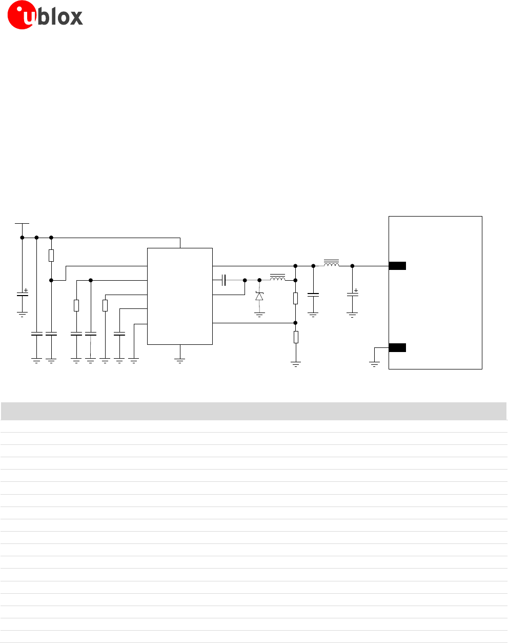
Figure 6 and the components listed in Table 4 show an example of a high reliability power supply circuit, where
the VCC module supply is provided by a step-down switching regulator capable to deliver 2.5 A current pulses,
with low output ripple, with 1 MHz fixed switching frequency in PWM mode operation. The use of a switching
regulator is suggested when the difference from the available supply rail and the VCC value is high: switching
regulators provide good efficiency transforming a 12 V supply to the 3.8 V typical value of the VCC supply. The
following power supply circuit example is implemented on the LEON Evaluation Board.
LEON-G100
LEON-G200
12V
C6
R3
C5
R2
C3C2
C1
R1
VIN
RUN
VC
RT
PG
SYNC
BD
BOOST
SW
FB
GND
6
7
10
9
5
C7
1
2
3
8
11
4
C8 C9
L2
D1
R4
R5
L1
C4
U1
50
VCC
GND
Figure 6: Suggested schematic design for the VCC voltage supply application circuit using a step-down regulator
Reference
Description
Part Number - Manufacturer
C1
47 µF Capacitor Aluminum 0810 50 V
MAL215371479E3 - Vishay
C2
10 µF Capacitor Ceramic X7R 5750 15% 50 V
C5750X7R1H106MB - TDK
C3
10 nF Capacitor Ceramic X7R 0402 10% 16 V
GRM155R71C103KA01 - Murata
C4
680 pF Capacitor Ceramic X7R 0402 10% 16 V
GRM155R71H681KA01 - Murata
C5
22 pF Capacitor Ceramic COG 0402 5% 25 V
GRM1555C1H220JZ01 - Murata
C6
10 nF Capacitor Ceramic X7R 0402 10% 16 V
GRM155R71C103KA01 - Murata
C7
470 nF Capacitor Ceramic X7R 0603 10% 25 V
GRM188R71E474KA12 - Murata
C8
22 µF Capacitor Ceramic X5R 1210 10% 25 V
GRM32ER61E226KE15 - Murata
C9
330 µF Capacitor Tantalum D_SIZE 6.3 V 45 mΩ
T520D337M006ATE045 - KEMET
D1
Schottky Diode 40 V 3 A
MBRA340T3G - ON Semiconductor
L1
10 µH Inductor 744066100 30% 3.6 A
744066100 - Wurth Electronics
L2
1 µH Inductor 7445601 20% 8.6 A
7445601 - Wurth Electronics
R1
470 kΩ Resistor 0402 5% 0.1 W
2322-705-87474-L - Yageo
R2
15 kΩ Resistor 0402 5% 0.1 W
2322-705-87153-L - Yageo
R3
33 kΩ Resistor 0402 5% 0.1 W
2322-705-87333-L - Yageo
R4
390 kΩ Resistor 0402 1% 0.063 W
RC0402FR-07390KL - Yageo
R5
100 kΩ Resistor 0402 5% 0.1 W
2322-705-70104-L - Yageo
U1
Step Down Regulator MSOP10 3.5 A 2.4 MHz
LT3972IMSE#PBF - Linear Technology
Table 4: Suggested components for VCC voltage supply application circuit using a high reliability step-down regulator
Figure 7 and the components listed in Table 5 show an example of a low cost power supply circuit, where the
VCC module supply is provided by a step-down switching regulator capable of delivering 2.5 A current pulses,
transforming a 12 V supply input.