
Integration Guide


Table Of Contents
- Preface
- Contents
- 1 System description
- 1.1 Overview
- 1.2 Architecture
- 1.3 Pin-out
- 1.4 Operating modes
- 1.5 Power management
- 1.6 System functions
- 1.7 RF connection
- 1.8 SIM interface
- 1.9 Serial Communication
- 1.10 Audio
- 1.11 ADC input (LEON-G100 only)
- 1.12 General Purpose Input/Output (GPIO)
- 1.13 M2M Setup Schematic Example
- 1.14 Approvals
- 2 Design-In
- 3 Handling and soldering
- 4 Product Testing
- Appendix
- A Extra Features
- B Glossary
- Related documents
- Revision history
- Contact
LEON-G100/G200 - System Integration Manual
GSM.G1-HW-09002-F3 Preliminary System description
Page 14 of 101
1.5 Power management
1.5.1 Power supply circuit overview
V_BCKP
GSM/GPRS Chipset
PSRAM
NOR Flash
MCP Memory
4-Bands GSM FEM
Antenna
Switch
PA
LDOs BB
LDOs RF
RTC
LDO
LDO EBU
Charging Control
1 µF
1 µF
LDO
VSIM
VCC
LEON-G100/G200
2 x 22 µF
2
35
50
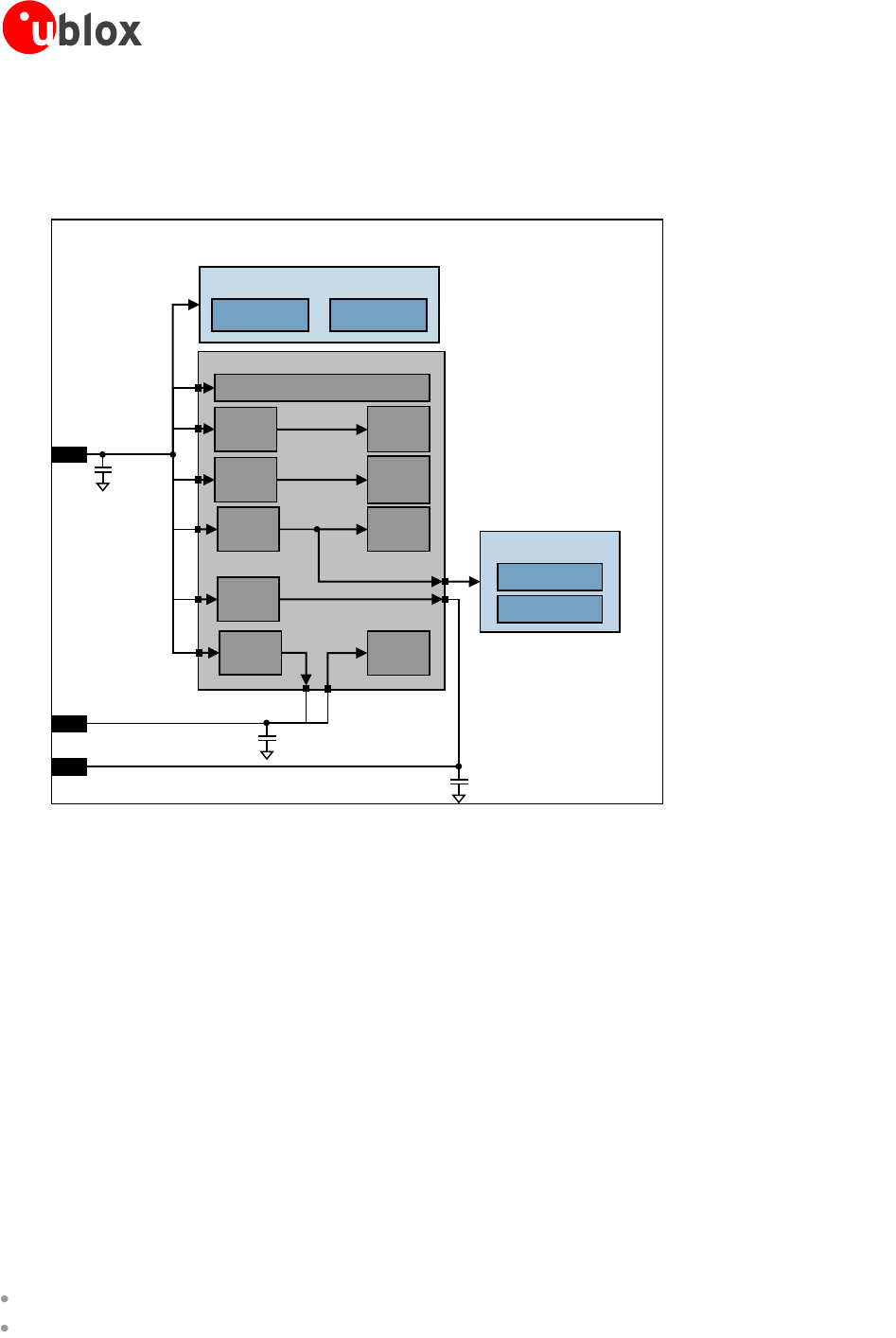
Figure 3: Power supply concept
Power supply is via VCC pin. This is the only one main power supply pin.
VCC pin connects the RF Power Amplifier and the integrated power management unit within the module: all
supply voltages needed by the module are generated from the VCC supply by integrated voltage regulators.
V_BCKP is the Real Time Clock (RTC) supply. When the VCC voltage is within the specified extended operating
range, the module supplies the RTC: 2.0 V typical are generated by the module on the V_BCKP pin. If the VCC
voltage is under the minimum specified extended limit, the RTC can be externally supplied via V_BCKP pin.
When a 1.8 V or a 3 V SIM card type is connected, LEON-G100/G200 automatically supply the SIM card via
VSIM pin. Activation and deactivation of the SIM interface with automatic voltage switch from 1.8 to 3 V is
implemented, in accordance to the ISO-IEC 78-16-e specifications.
The integrated power management unit also provides the control state machine for system start up, including
start up with discharged batteries, pre-charging and system reset control.
LEON-G100/G200 feature a power management concept optimized for most efficient use of battery power. This
is achieved by hardware design utilizing power efficient circuit topology, and by power management software
controlling the power saving configuration of the module. Battery management runs in the context of the
operation and maintenance process:
Battery charging control, in order to maintain the full capacity of the battery
Collecting and processing of measurements of battery voltage