
Integration Guide
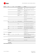
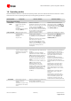


Table Of Contents
- Preface
- Contents
- 1 System description
- 1.1 Overview
- 1.2 Architecture
- 1.3 Pin-out
- 1.4 Operating modes
- 1.5 Power management
- 1.6 System functions
- 1.7 RF connection
- 1.8 SIM interface
- 1.9 Serial Communication
- 1.10 Audio
- 1.11 ADC input (LEON-G100 only)
- 1.12 General Purpose Input/Output (GPIO)
- 1.13 M2M Setup Schematic Example
- 1.14 Approvals
- 2 Design-In
- 3 Handling and soldering
- 4 Product Testing
- Appendix
- A Extra Features
- B Glossary
- Related documents
- Revision history
- Contact

LEON-G100/G200 - System Integration Manual
GSM.G1-HW-09002-F3 Preliminary System description
Page 12 of 101
1.4 Operating modes
LEON-G100/G200 modules include several operating modes, each have different features and interfaces. Table 2
summarizes the various operating modes and provides general guidelines for operation.
Operating Mode
Description
Features / Remarks
Transition condition
General Status: Power-down
Not-Powered
Mode
VCC supply not present or
below normal operating
range.
Microprocessor not
operating.
RTC only operates if supplied
through V_BCKP pin.
Module is switched off.
Application interfaces are not accessible.
Internal RTC timer operates only if a valid
voltage is applied to V_BCKP pin.
Any external signal connected to UART
I/F, I
2
S I/F, HS_DET, or a GPIO must be set
low or tri-stated to avoid an increase of
module power-off consumption.
Module cannot be switched on by a
falling edge provided on the PWR_ON
input, neither by a preset RTC alarm, nor
by charger detection on the V_CHARGE
and CHARGE_SENSE pins.
Power-Off Mode
VCC supply within normal
operating range.
Microprocessor not
operating.
Only RTC runs.
Module is switched off: normal
shutdown after sending the
AT+CPWROFF command (refer to u-blox
2G GSM/GPRS AT Commands Manual
[2]).
Application interfaces are not accessible.
Only internal RTC in operation.
Any external signal connected to the
UART I/F, I
2
S I/F, HS_DET pin, or a GPIO
must be set low or tri-stated to avoid an
increase of the module power-off
consumption.
Module can be switched on by a falling
edge provided on the PWR_ON input, by
a preset RTC alarm, or by charger
detection on the V_CHARGE and
CHARGE_SENSE pins.
General Status: Normal Operation
Idle-Mode
Microprocessor runs with
32 kHz as reference oscillator.
Module does not accept data
signals from an external
device.
If power saving is enabled, the module
automatically enters idle mode whenever
possible.
Application interfaces are disabled.
If hardware flow control is enabled, the
CTS line indicates when the module is in
idle (power saving configuration): the
line is driven in the OFF state when the
module is not prepared to accept data
signals.
If hardware flow control is disabled, the
CTS line is fixed to ON state.
Module by default is not set to
automatically enter in idle mode
whenever possible, unless power saving
configuration is enabled by appropriate
AT command (refer to u-blox 2G
GSM/GPRS AT Commands Manual [2],
AT+UPSV).
If the module is registered with the
network and power saving is enabled, it
automatically goes in idle mode and
periodically wakes up to active mode to
monitor the paging channel for the
paging block reception according to
network indication.
If module is not registered with the
network and power saving is enabled, it
automatically enters idle mode and
periodically wakes up to monitor external
activity.
Module wakes up from idle mode to
active mode if an RTC alarm occurs.
Module wakes up from idle mode to
active mode when data is received on
UART interface (refer to 1.9.1 for more
details).
Module wakes up from idle mode to
active mode if a voice or data call
incoming.
Module wakes up from idle mode to
active mode when the RTS input line is
set to the ON state by the DTE if the
AT+UPSV=2 command is sent to the
module (feature not enabled by default).
Active-Mode
Microprocessor runs with
26 MHz as reference
oscillator.
The module is ready to accept
data signals from an external
device.
Module is switched on and is fully active:
power saving is not enabled.
The application interfaces are enabled.