
User`s manual


IMS-9000 User’s Manual
Notice: No part of this document may be reproduced, copied or distributed without Page 9
written permission from Delphi Display Systems, INC.
Copyright ©2000. [Unpublished Work]. All rights reserved.
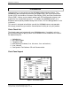
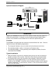
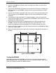
System Connection Diagram
Laptop or Desktop PC
Modem
RS232
Serial
Cable
Point of Sale Terminal
Back Office PC
(Optional)
PC (optional)
Line Phone
PWR
POS
OCS
RS232 / RS422
I/O Cable
RS232
Serial
Cable
Telephone
Delphi
Order Confirmation System
Telephone
Cord
Telephone
Company
Phone
Line
Phone
Line
Telephone
Cord
Delphi
IMS9000 Intelligent Modem Switch
Figure 3 - System Connection Diagram
Installation
Unpack your IMS9000 and verify that all of the contents listed in the Parts Check List
section are accounted for. If any parts are missing, please contact Delphi Display
Systems at the number listed in the back of this manual for replacement parts.
Location
The IMS9000 is designed to be wall mounted in the back office of the store. Choose a
location that meets the following requirements:
• The front panel indicators are easily visible and can be observed at all times.
• The mounting location is within six (6) feet of an AC power outlet.
• The mounting location is in close proximity to the telephone (modem) line to be
connected to the IMS9000.
Typical Installation
1. Mark the locations of the two (2) mounting screw holes on the wall in the desired
location at exactly 3.50” on center. Refer to the Rear Panel Layout figure below.
2. Drill two pilot holes and install the two #8 screws provided. Allow each screw to
protrude from the wall approximately 1/8” so that it will lock into the rear panel
keyholes of the IMS9000. In locations where installing to drywall, use the supplied
anchors if necessary. To install anchors, drill two ¼” holes and insert the anchors
flush to the wall surface.