
User`s manual


IMS-9000 User’s Manual
Notice: No part of this document may be reproduced, copied or distributed without Page 7
written permission from Delphi Display Systems, INC.
Copyright ©2000. [Unpublished Work]. All rights reserved.
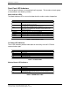
POS Status LED Indicators
LED Indicator Function
TXD Transmit Data.
RXD Receive Data.
RTS Request to Send.
CTS Clear to Send.
DTR Data Terminal Ready.
DSR Data Set Ready.
Table 4 - POS Status LEDs
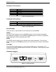
OCS Status LED Indicators
LED Indicator Function
TXD Transmit Data. This LED flashes when data is transmitted to the OCS.
RXD Receive Data. This LED flashes when data is received from the OCS.
PASS OCS Test Status Indicator. GREEN indicates Pass, RED indicates Fail.
Table 5 - OCS Status LEDs
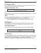
Push Buttons
There are three (3) push buttons on the front panel of the IMS9000.
RESET
The RESET push button resets the IMS9000 and puts it into its power-up condition.
Any telephone connections are immediately dropped and the unit returns to Automatic
mode of operation (POS connected to the OCS).
MODE
The MODE switch manually cycles through each mode of operation. Each time the
button is pressed, the IMS9000 advances to the next mode until it returns to Automatic
mode.
OCS TEST
The OCS TEST button performs a self-test of the OCS when it is connected. The
results of the self-test are displayed on the PASS LED indicator. Green indicates PASS
and Red indicates FAIL.
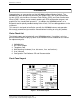
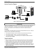
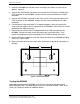
Connector Layout
PC (optional)
Line Phone
PWR
POS
OCS
Figure 2 - Connector Layout