
User`s manual


IMS-9000 User’s Manual
Notice: No part of this document may be reproduced, copied or distributed without Page 6
written permission from Delphi Display Systems, INC.
Copyright ©2000. [Unpublished Work]. All rights reserved.
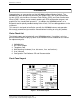
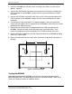
Front Panel LED Indicators
The front panel indicators are organized into five groups. The functions of each group
are described in the following sections.
Mode Indicator LEDs
The Mode Indicator LEDs are used to determine the various modes of operation.
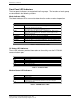
LED Indicator Function
REQ Flashes when a mode change request is made. A mode change request can
come from the MODEM (call answer or hang up), or from an external PC
connected to the PC port connection.
AUTO Flashes in a heart beat pattern during Automatic mode of operation. This is
the default mode of operation after power-up or reset.
RS485 When ON, indicates the OCS interface is in RS485 mode. When off, the
OCS interface is in RS232 mode. This mode is set via a jumper on the
IMS9000 circuit board.
OCS-PC Indicates the OCS is connected to the PC port.
PC-MODEM Indicates the PC port is connected to the MODEM.
OCS-MODEM Indicates the OCS is connected to the MODEM.
POS-PC Indicates the POS is connected to the PC port.
OCS-POS Indicates the OCS is connected to the POS port. This is the default mode of
operation after power-up or reset.
POS-MODEM Indicates the POS port is connected to the MODEM.
Table 1 – Mode Indicator LEDs
PC Status LED Indicators
These LED indicators provide information on the activity over the PC RS232
communications port.
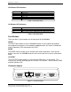
LED Indicator Function
TXD Transmit Data.
RXD Receive Data.
RTS Request to Send.
CTS Clear to Send.
DTR Data Terminal Ready.
DSR Data Set Ready.
Table 2 - PC Status LEDs
Modem Status LED Indicators
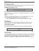
LED Indicator Function
TXD Transmit Data.
RXD Receive Data.
DCD Data Carrier Detect. This LED is illuminated when a telephone connection is
established and remains illuminated until the connection is dropped.
DTR Data Terminal Ready.
Table 3 - MODEM Status LEDs