IMS-9000 Intelligent Modem Switch USER’S MANUAL Document Part #: RDC-HDWIMS9K100
IMS-9000 User’s Manual © 2000 Delphi Display Systems, INC. All rights reserved. Delphi Display Systems, INC. (Delphi) reserves the right to revise or update its products and documents without notification. Delphi makes no guarantee, implied or expressed regarding the suitability of its products for any particular purpose, nor does Delphi assume any liability arising out of the application of use of any of its products or circuits, whether used properly or improperly.
IMS-9000 User’s Manual Contents IMPORTANT SAFETY INSTRUCTIONS ..............................................................................................................4 INTRODUCTION .......................................................................................................................................................5 PARTS CHECK LIST ....................................................................................................................................................
IMS-9000 User’s Manual List of Figures FIGURE 1 - FRONT PANEL LAYOUT.................................................................................................................................5 FIGURE 2 - CONNECTOR LAYOUT ...................................................................................................................................7 FIGURE 3 - SYSTEM CONNECTION DIAGRAM .................................................................................................................
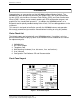
IMS-9000 User’s Manual Introduction Congratulations on your purchase of the IMS9000 Intelligent Modem Switch. The IMS9000 has been designed to work with your Delphi Drive-Thru Order Confirmation System (OCS) also known as Customer Order Display (COD) and Order Confirmation Board (OCB). It allows you to remotely update your OCS configuration, daypart, and graphic files via standard dial up access.
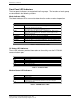
IMS-9000 User’s Manual Front Panel LED Indicators The front panel indicators are organized into five groups. The functions of each group are described in the following sections. Mode Indicator LEDs The Mode Indicator LEDs are used to determine the various modes of operation. LED Indicator Function REQ Flashes when a mode change request is made. A mode change request can come from the MODEM (call answer or hang up), or from an external PC connected to the PC port connection.
IMS-9000 User’s Manual POS Status LED Indicators LED Indicator Function TXD RXD RTS CTS DTR DSR Transmit Data. Receive Data. Request to Send. Clear to Send. Data Terminal Ready. Data Set Ready. Table 4 - POS Status LEDs OCS Status LED Indicators LED Indicator Function TXD RXD PASS Transmit Data. This LED flashes when data is transmitted to the OCS. Receive Data. This LED flashes when data is received from the OCS. OCS Test Status Indicator. GREEN indicates Pass, RED indicates Fail.
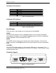
IMS-9000 User’s Manual PC Connector – DB9F The PC connector allows a direct connection to a PC serial communication port via a standard straight-through wired serial extension cable. Telephone Connectors – RJ11 CAUTION: TO REDUCE THE RISK OF FIRE, USE NO.26AWG OR LARGER TELECOMMUNICATION LINE CORD. Line The Line connector is used to connect the IMS9000 to the telephone line via a standard telephone cord (supplied).
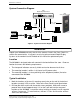
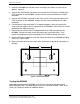
IMS-9000 User’s Manual System Connection Diagram Delphi IMS9000 Intelligent Modem Switch Delphi Order Confirmation System PC (optional) Line Phone POS PWR RS232 / RS422 I/O Cable RS232 Serial Cable Telephone Cord Back Office PC (Optional) OCS RS232 Serial Cable Telephone Cord Point of Sale Terminal Modem Phone Line Telephone Company Phone Line Laptop or Desktop PC Telephone Figure 3 - System Connection Diagram Installation Unpack your IMS9000 and verify that all of the contents listed in th
IMS-9000 User’s Manual 3. Install the IMS9000 over the two screws and adjust the screws as necessary to obtain a secure fit. 4. Connect the DB9 Female connector on the end of the OCS Serial I/O Cable to the OCS connector on the IMS9000. Secure with the screws provided on the cable connector. 5. Connect the DB9 Male connector of the Point of Sale serial extension cable to the POS connector on the IMS9000. Secure with the screws provided on the cable connector. 6.
IMS-9000 User’s Manual Software Installation Please refer to the documentation included with the software CD for installation and user instructions. Modes of Operation Power Off Mode The IMS9000 is designed to provide uninterrupted operation in the event of a loss of power. If the IMS9000 loses power, it will connect the POS directly to the OCS so that orders can be processed normally without interruption. This only applies to RS232 OCS configurations.
IMS-9000 User’s Manual up, the IMS9000 restores the OCS-POS connection allowing normal operation to resume. Figure 6 - Modem/OCS Connection Indicators (Automatic Mode) PC Connection Request In Automatic mode, a local back office or laptop PC can make a request for a direct connection to the OCS. The remote PC must be connected to the IMS9000 PC port connector via a RS232 serial data cable and be running Delphi’s OCS Configuration Tool software to be properly authenticated.
IMS-9000 User’s Manual Manual Mode 2 – OCS ↔ MODEM, POS ↔ PC Communication is established between the OCS and the MODEM as well as between the Point Of Sale (POS) terminal and the PC port. Figure 8 - Manual Mode 2 Indicators Manual Mode 3 – OCS ↔ PC, POS ↔ MODEM Communication is established between the OCS and the PC port as well as between the Point Of Sale (POS) terminal and the MODEM port.
IMS-9000 User’s Manual In Case of Difficulty If you have difficulty, refer to the following table for solutions to some common problems. If you continue to have difficulty, contact Delphi Display Systems technical support. PROBLEM POSSIBLE CAUSE(S) CORRECTIVE ACTION(S) No LED indicators are active on the IMS9000 No Power to the IMS9000 Make sure the AC Power Adapter is plugged into a live AC outlet and that the power connector is properly plugged into the power jack on the IMS9000.
IMS-9000 User’s Manual STANDARD LIMITED WARRANTY Delphi Display Systems, INC. (“Delphi”) warrants this Product against defects in material or workmanship as follows: Limited Warranty LABOR: For a period of twelve (12) months from the date of purchase, if this Product is determined to be defective, Delphi will repair or replace the product with a new or rebuilt unit at no charge, or pay the labor charges to any Delphi authorized service facility.
IMS-9000 User’s Manual IMS9000 Technical Specifications AC Power Adapter • • • Input Voltage: Frequency: Power: 120 VAC 60 Hz. 8W IMS9000 Unit • • • • • • Input Voltage: Modem Serial Interfaces: PC Phone / Line POS OCS Operating Temperatures: Dimensions: Weight: 8-24 VDC or 15-24 VAC V.34 / V.32 bis (33.6 kbps) RS-232C, DB9F Std. Telco, RJ11 RS-232C, DB9F RS-232C, RS-422/RS-485, DB9M (Optically Isolated) 50° to 120° F (ambient) 6.125 ”W X 1.5”H X 4.25”D 10.9 oz.