
Installation manual


SINGLE SPLIT
4 English 11/2002
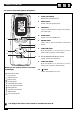
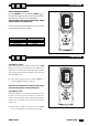
IDENTIFICATION OF THE PARTS
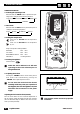
AUTO
TEST
RUN
STOP
AUTO
STOP
1
4
5
11
10
7
9
6
8
12
4
4
14
13
2
3
Air inlet
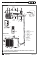
INDOOR UNIT
OUTDOOR UNIT
The above figure represents a simplified layout of the appliance and may not correspond to the
appearance of the unit actually purchased.
U I A
Air outlet
Air inlet
Air outlet
1Front panel
2 Air filter
3 Electrostatic filter (optional)
4 Manual switch
5 Cable panel
6 Activated carbon filter
7 Louvers
8 Signal receiver
9 LED display
10 Power plug
11 Drain hose
12 Remote control
13 Handle
14 Air outlet grill
4
AUTO
STOP
RUN
TEST