
Installation and Operation Guide


13
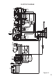
CONNECTION OF THE POWER SUPPLY CABLE
Important! This cooker must be connected to the electricity supply only by an
authorised person.
To connect the feeder cable to the cooker it is necessary to:
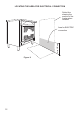
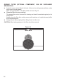
• Remove the two screws that hold shield “A” behind the cooker (g. 12).
• Open completely the cable clamp “D”.
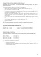
• Fitted with a 6-pole terminal block, position the U bolts onto terminal block ‘B’ (g. 12)
according to the diagrams in gs. 13 - 14.
• Feed the supply cable through the cable clamp “D”. The supply cable must be of a
suitable size for the current requirements of the appliance; see the section “Feeder
cable section”.
• Connect the phase, neutral and earth wires to terminal “B” according to gures 13 and
14.
• Pull the feeder cable and block it with the cable clamp “D”.
• Re-mount shield “A”.
N.B. The earth conductor must be left about 3 cm longer than the others.
VOLTAGE AND POWER CONSUMPTION
230/400 V 3N 50 Hz 11900 W (51.74 A) (diversity not applied)
240/415 V 3N 50 Hz 12950 W (53.96 A) (diversity not applied)
FEEDER CABLE SECTION
This cooker must be connected to electrical supply using V105 insulated cable.
230 V~, 240 V~ 3 x 6 mm
2
(*)
230 V 3~, 240 V~ 4 x 4 mm
2
(*)
400 V 3N~, 415 V 3N~ 5 x 2,5 mm
2
(*)
400 V 2N~, 415 V 2N~ 4 x 4 mm
2
(*)
(*) Connection with wall box connection.
– Diversity factor applied.
– A diversity factor may be applied to the total loading of the appliance only by a
suitably qualied person.