
Reference Guide


Table Of Contents
13
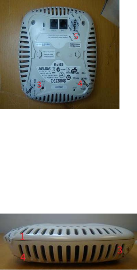
3.2.3 AP-135 TEL Placement
This section displays all the TEL locations of the Aruba AP-135. The AP-135 requires a minimum of 5
TELs to be applied as follows:
3.2.3.1 To detect opening of the chassis cover:
1. Spanning the bottom and top chassis covers and placed in the front left corner
2. Spanning the bottom and top chassis covers and placed in the back left corner
3. Spanning the chassis screw on the bottom left corner
4. Spanning the chassis screw on the bottom right corner
3.2.3.2 To detect access to restricted ports
5. Spanning the serial port
Following is the TEL placement for the AP-135:
Figure 7: AP-135 Front view