
Users Guide


12 Fibre Channel Cluster Setup
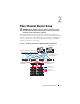
Table 2-1. Fibre Channel Hardware Interconnections
Cluster Component Connections
Dell PowerEdge
system node
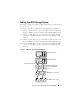
• One Category 5 enhanced (CAT 5e) or CAT 6 cable from the
public NIC to
the LAN
• One CAT 5e or CAT 6 cable from the private Gigabit NIC to
the Gigabit Ethernet switch
• One CAT 5e or CAT 6 cable from a redundant private
Gigabit
NIC to a redundant Gigabit Ethernet switch
• One fiber optic cable from HBA 0 to Fibre Channel switch 0
• One fiber optic cable from HBA 1 to Fibre Channel switch 1
Dell/EMC Fibre
Channel storage
system
• Two CAT 5e or CAT 6 cables connected to the LAN
• One to four fiber optic cable connections to each Fibre
Channel switch. For
example, for a four-port configuration:
–One
fiber optic cable
from SPA port 0 to Fibre Channel
switch 0
–One
fiber optic cable
from SPA port 1 to Fibre Channel
switch 1
–One
fiber optic cable
from SPB port 0 to Fibre Channel
switch 1
•One
fiber optic cable
from SPB port 1 to Fibre Channel switch 0
Dell/EMC Fibre
Channel switch
• One to four fiber optic cable connections to the
Dell/EMC
Fibre Channel storage system
• One fiber optic cable connection to each PowerEdge
system
HBA
Gigabit Ethernet
switch
• One CAT 5e or CAT 6 connection to the private Gigabit NIC
on each PowerEdge system
• One CAT 5e or CAT 6 connection to the remaining Gigabit
Ethernet switch