Dell™ Studio™ 1569 Service Manual Before You Begin Battery Memory Module(s) Wireless Mini-Card(s) Power Button Panel Keyboard Palm Rest Internal Card With Bluetooth® Wireless Technology Hard Drive Optical Drive Processor Fan USB/Audio Board Speakers System Board Coin-Cell Battery Processor Heat Sink Processor Module Display Camera Module Flashing the BIOS Notes, Cautions, and Warnings NOTE: A NOTE indicates important information that helps you make better use of your computer.
Back to Contents Page Battery Dell™ Studio™ 1569 Service Manual Removing the Battery Replacing the Battery Before working inside your computer, read the safety information that shipped with your computer. For additional safety best practices information, see the Regulatory Compliance Homepage at www.dell.com/regulatory_compliance. CAUTION: Only a certified service technician should perform repairs on your computer. Damage due to servicing that is not authorized by Dell™ is not covered by your warranty.
Back to Contents Page Before You Begin Dell™ Studio™ 1569 Service Manual Recommended Tools Turning Off Your Computer Before Working Inside Your Computer This manual provides procedures for removing and installing components in your computer. Unless otherwise noted, each procedure assumes that the following conditions exist: l You have performed the steps in Turning Off Your Computer and Before Working Inside Your Computer. l You have read the safety information that shipped with your computer.
3. If your computer is connected to a docking device, disconnect it. See the documentation that came with your docking device for instructions. CAUTION: To disconnect a network cable, first unplug the cable from your computer and then unplug the cable from the network device. 4. Disconnect all telephone or network cables from the computer. 5. Eject any cards from your computer, if applicable. 6. Disconnect your computer and all attached devices from their electrical outlets. 7.
Back to Contents Page Flashing the BIOS Dell™ Studio™ 1569 Service Manual 1. Turn on the computer. 2. Go to support.dell.com. 3. Click Drivers & Downloads® Select Model. 4. Locate the BIOS update file for your computer: NOTE: The Service Tag for your computer is located at the bottom of the computer. If you have your computer's Service Tag: a. Click Enter a Service Tag. b. Enter your computer's Service Tag in the Enter a service tag: field, click Go, and proceed to step 5.
Back to Contents Page Internal Card With Bluetooth® Wireless Technology Dell™ Studio™ 1569 Service Manual Removing the Bluetooth Card Replacing the Bluetooth Card Before working inside your computer, read the safety information that shipped with your computer. For additional safety best practices information, see the Regulatory Compliance Homepage at www.dell.com/regulatory_compliance. CAUTION: Only a certified service technician should perform repairs on your computer.
. Replace the battery (see Replacing the Battery). CAUTION: Before turning on the computer, replace all screws and ensure that no stray screws remain inside the computer. Failure to do so may result in damage to the computer.
Back to Contents Page Camera Module Dell™ Studio™ 1569 Service Manual Removing the Camera Module Replacing the Camera Module Before working inside your computer, read the safety information that shipped with your computer. For additional safety best practices information, see the Regulatory Compliance Homepage at www.dell.com/regulatory_compliance. CAUTION: Only a certified service technician should perform repairs on your computer.
6. Replace the display bezel (see Replacing the Display Bezel). 7. Replace the display assembly (see Replacing the Display Assembly). 8. Replace the battery (see Replacing the Battery). CAUTION: Before turning on the computer, replace all screws and ensure that no stray screws remain inside the computer. Failure to do so may result in damage to the computer.
Back to Contents Page Coin-Cell Battery Dell™ Studio™ 1569 Service Manual Removing the Coin-Cell Battery Replacing the Coin-Cell Battery Before working inside your computer, read the safety information that shipped with your computer. For additional safety best practices information, see the Regulatory Compliance Homepage at www.dell.com/regulatory_compliance. CAUTION: Only a certified service technician should perform repairs on your computer.
Back to Contents Page
Back to Contents Page Processor Module Dell™ Studio™ 1569 Service Manual Removing the Processor Module Replacing the Processor Module Before working inside your computer, read the safety information that shipped with your computer. For additional safety best practices information, see the Regulatory Compliance Homepage at www.dell.com/regulatory_compliance. CAUTION: Only a certified service technician should perform repairs on your computer.
Replacing the Processor Module NOTE: If a new processor is installed, you will receive a new thermal-cooling assembly, which will include an affixed thermal pad, or you will receive a new thermal pad along with documentation to illustrate proper installation. 1. Follow the procedures in Before You Begin. 2. Align the pin-1 corner of the processor module with the pin-1 corner of the ZIF socket, then insert the processor module.
Back to Contents Page Processor Heat Sink Dell™ Studio™ 1569 Service Manual Removing the Processor Heat Sink Replacing the Processor Heat Sink Before working inside your computer, read the safety information that shipped with your computer. For additional safety best practices information, see the Regulatory Compliance Homepage at www.dell.com/regulatory_compliance. If you remove the processor heat sink from the computer when the heat sink is hot, do not touch the metal housing of the processor heat sink.
5. Replace the battery (see Replacing the Battery). CAUTION: Before turning on the computer, replace all screws and ensure that no stray screws remain inside the computer. Failure to do so may result in damage to the computer.
Back to Contents Page Display Dell™ Studio™ 1569 Service Manual Display Assembly Display Bezel Display Panel Display Hinges and Brackets Before working inside your computer, read the safety information that shipped with your computer. For additional safety best practices information, see the Regulatory Compliance Homepage at www.dell.com/regulatory_compliance. CAUTION: Only a certified service technician should perform repairs on your computer.
Replacing the Display Assembly 1. Follow the procedures in Before You Begin. 2. Use the alignment posts to place the display assembly on the computer base. 3. Replace the five screws that secure the display assembly to the computer base. 4. Replace the display cable grounding screw in the display hinge. 5. Route the Mini-Card antenna cables in the routing guides on the computer base. 1 Mini-Card antenna cables 2 computer base 6.
1 screws (4) 3 display bezel 2 rubber pads (4) Replacing the Display Bezel 1. Follow the procedures in Before You Begin. 2. Ensure the display and Mini-Card cables route through the hinge portion of the display bezel, and snap the display bezel onto the display assembly. 3. Replace the four screws that secure the display bezel to the display assembly. 4. Replace the four rubber pads that cover the display bezel screws. 5. Replace the display assembly (see Replacing the Display Assembly). 6.
1 screws (4) 3 display cover 6. 2 display panel Pull the pull-tab to disconnect the display cable from the display panel. 1 display panel 3 display cable 2 pull-tab Replacing the Display Panel 1. Follow the procedures in Before You Begin. 2. Connect the display cable to the connector on the back of the display panel. 3. Use the alignment posts to place the display panel on the display cover. 4. Replace the four screws that secure the display panel to the display cover. 5.
Removing the Display Hinges and Brackets 1. Follow the procedures in Before You Begin. 2. Remove the display assembly (see Removing the Display Assembly). 3. Remove the display bezel (see Removing the Display Bezel). 4. Remove the display panel (see Removing the Display Panel). 5. Remove the four screws that secure the display hinges and brackets to the display cover. 1 display cover 3 display hinges and brackets (2) 2 screws (4) Replacing the Display Hinges and Brackets 1.
Back to Contents Page Processor Fan Dell™ Studio™ 1569 Service Manual Removing the Processor Fan Replacing the Processor Fan Before working inside your computer, read the safety information that shipped with your computer. For additional safety best practices information, see the Regulatory Compliance Homepage at www.dell.com/regulatory_compliance. CAUTION: Only a certified service technician should perform repairs on your computer.
3. Replace the two screws that secure the processor fan to the computer base. 4. Connect the processor fan cable to the system board connector. 5. Replace the palm rest (see Replacing the Palm Rest). 6. Replace the keyboard (see Replacing the Keyboard). 7. Replace the power button panel (see Replacing the Power Button Panel). 8. Replace the battery (see Replacing the Battery). CAUTION: Before turning on the computer, replace all screws and ensure that no stray screws remain inside the computer.
Back to Contents Page Hard Drive Dell™ Studio™ 1569 Service Manual Removing the Hard Drive Replacing the Hard Drive Before working inside your computer, read the safety information that shipped with your computer. For additional safety best practices information, see the Regulatory Compliance Homepage at www.dell.com/regulatory_compliance. If you remove the hard drive from the computer when the drive is hot, do not touch the metal housing of the hard drive.
1 connector latch 2 pull-tab 3 audio cable 4 screws (4) 5 hard drive assembly 6 interposer 7 hard drive cable 10. Remove the four screws that secure the hard drive bracket to the hard drive. 11. Remove the hard drive from the hard drive bracket. 1 hard drive 3 screws (4) 2 hard drive bracket Replacing the Hard Drive 1. Follow the procedures in Before You Begin. 2. Remove the new hard drive from its packaging. Save the original packaging for storing or shipping the hard drive. 3.
Back to Contents Page Keyboard Dell™ Studio™ 1569 Service Manual Removing the Keyboard Replacing the Keyboard Before working inside your computer, read the safety information that shipped with your computer. For additional safety best practices information, see the Regulatory Compliance Homepage at www.dell.com/regulatory_compliance. CAUTION: Only a certified service technician should perform repairs on your computer. Damage due to servicing that is not authorized by Dell™ is not covered by your warranty.
7 keyboard backlight cable 9 screw 8 palm rest Replacing the Keyboard 1. Follow the procedures in Before You Begin. 2. Place the keyboard upside down on the palm rest and connect the keyboard cables. a. b. Slide the keyboard cable into the system board connector and press the connector tabs into the connector to secure the cable. If you have a backlit keyboard, slide the keyboard backlight cable into the system board connector and press down on the connector latch to secure the cable. 3.
Back to Contents Page Memory Module(s) Dell™ Studio™ 1569 Service Manual Removing the Memory Module(s) Replacing the Memory Module(s) Before working inside your computer, read the safety information that shipped with your computer. For additional safety best practices information, see the Regulatory Compliance Homepage at www.dell.com/regulatory_compliance. CAUTION: Only a certified service technician should perform repairs on your computer.
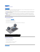
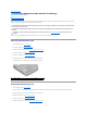
1 memory module connector 3 memory module 2 securing clips (2) Replacing the Memory Module(s) CAUTION: If you need to install memory modules in two connectors, install a memory module in the connector labeled "DIMM A" before you install a memory module in the connector labeled "DIMM B." 1. Follow the procedures in Before You Begin. 2. Align the notch in the memory module with the tab in the memory module connector. 3.
Back to Contents Page Wireless Mini-Card(s) Dell™ Studio™ 1569 Service Manual Removing the Mini-Card(s) Replacing the Mini-Card(s) Before working inside your computer, read the safety information that shipped with your computer. For additional safety best practices information, see the Regulatory Compliance Homepage at www.dell.com/regulatory_compliance. CAUTION: Only a certified service technician should perform repairs on your computer.
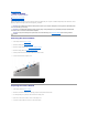
1 antenna cables (2) 2 Mini-Card 3 screw 4 system board connector 7. Lift the Mini-Card out of the system board connector. Replacing the Mini-Card(s) 1. Follow the procedures in Before You Begin. 2. Remove the new Mini-Card from its packaging. CAUTION: Use firm and even pressure to slide the card into place. If you use excessive force, you may damage the connector. CAUTION: The connectors are keyed to ensure correct insertion.
6. Secure unused antenna cables in the protective mylar sleeve. 7. Replace the Mini-Card cover and tighten the two captive screws that secure the Mini-Card cover to the computer base. 8. Replace the battery (see Replacing the Battery). CAUTION: Before turning on the computer, replace all screws and ensure that no stray screws remain inside the computer. Failure to do so may result in damage to the computer. 9. Install the drivers and utilities for your computer, as required.
Back to Contents Page Optical Drive Dell™ Studio™ 1569 Service Manual Removing the Optical Drive Replacing the Optical Drive Before working inside your computer, read the safety information that shipped with your computer. For additional safety best practices information, see the Regulatory Compliance Homepage at www.dell.com/regulatory_compliance. CAUTION: Only a certified service technician should perform repairs on your computer.
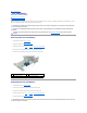
1 optical drive assembly 2 screws (5) 8. Disconnect the optical drive interposer from the optical drive. 9. Remove the four screws (two on each side) that secure the optical drive brackets to the optical drive. 1 optical drive 2 brackets (2) 3 screws (4) 4 optical drive interposer Replacing the Optical Drive 1. Follow the procedures in Before You Begin. 2. Replace the four screws (two on each side) that secure the optical drive brackets to the optical drive. 3.
Back to Contents Page Palm Rest Dell™ Studio™ 1569 Service Manual Removing the Palm Rest Replacing the Palm Rest Before working inside your computer, read the safety information that shipped with your computer. For additional safety best practices information, see the Regulatory Compliance Homepage at www.dell.com/regulatory_compliance. CAUTION: To avoid electrostatic discharge, ground yourself by using a wrist grounding strap or by periodically touching an unpainted metal surface.
1 palm rest 2 screws (6) 3 routing guides 4 speaker cable 5 latch connector 6 pull-tab 7 touch pad cable CAUTION: Carefully separate the palm rest from the computer base to avoid damage to the palm rest. 11. Turn the computer over. 12. In the battery bay, use a plastic scribe to disengage the tabs on the palm rest. 1 battery bay 2 tabs (4) 13. Turn the computer over and open the display as far as possible. 14.
Replacing the Palm Rest 1. Follow the procedures in Before You Begin. 2. Align the palm rest on the computer base and snap the palm rest into place. 3. Slide the touch pad cable into the system board connector and press down on the connector latch to secure the cable. 4. Replace the six screws that secure the palm rest to the computer base. 5. Replace the keyboard (see Replacing the Keyboard). 6. Replace the power button panel (see Replacing the Power Button Panel). 7.
Back to Contents Page Power Button Panel Dell™ Studio™ 1569 Service Manual Removing the Power Button Panel Replacing the Power Button Panel Before working inside your computer, read the safety information that shipped with your computer. For additional safety best practices information, see the Regulatory Compliance Homepage at www.dell.com/regulatory_compliance. CAUTION: Only a certified service technician should perform repairs on your computer.
1 power button cable 3 palm rest 2 power button panel Replacing the Power Button Panel 1. Follow the procedures in Before You Begin. 2. Connect the power button cable to the system board connector. 3. Slide the tabs on the power button panel into the slots on the palm rest and snap the power button panel into place. 4. Close the computer and turn it over. 5. Replace the two screws that secure the power button panel to the computer base. 6. Replace the battery (see Replacing the Battery).
Back to Contents Page Speakers Dell™ Studio™ 1569 Service Manual Removing the Speakers Replacing the Speakers Before working inside your computer, read the safety information that shipped with your computer. For additional safety best practices information, see the Regulatory Compliance Homepage at www.dell.com/regulatory_compliance. CAUTION: Only a certified service technician should perform repairs on your computer. Damage due to servicing that is not authorized by Dell™ is not covered by your warranty.
3. Route the speaker cable and connect it to the USB/audio board connector. 4. Replace one screw on the left speaker and two screws on the right speaker. 5. Replace the optical drive (see Replacing the Optical Drive). 6. Replace the palm rest (see Replacing the Palm Rest). 7. Replace the keyboard (see Replacing the Keyboard). 8. Replace the power button panel (see Replacing the Power Button Panel). 9. Replace the battery (see Replacing the Battery).
Back to Contents Page System Board Dell™ Studio™ 1569 Service Manual Removing the System Board Replacing the System Board Entering the Service Tag in the BIOS Before working inside your computer, read the safety information that shipped with your computer. For additional safety best practices information, see the Regulatory Compliance Homepage at www.dell.com/regulatory_compliance. CAUTION: Only a certified service technician should perform repairs on your computer.
1 system board assembly 2 screws (3) 3 pull-tab 4 display cable 5 USB cable 6 pull-tab 7 computer base 8 hard drive cable 9 pull-tab 16. Carefully ease the connectors on the system board out of the computer base and lift the system board assembly out of the computer base. 17. Turn the system board assembly over. 18. Follow the instructions from step 4 to step 5 in Removing the Coin-Cell Battery. 19. Remove the processor heat sink (see Removing the Processor Heat Sink). 20.
15. Replace the Bluetooth card (see Replacing the Bluetooth Card). 16. Replace the palm rest (see Replacing the Palm Rest). 17. Replace the power button panel (see Replacing the Power Button Panel). 18. Replace the keyboard (see Replacing the Keyboard). 19. Replace the Mini-Card(s) (see Replacing the Mini-Card(s)). 20. Replace the memory module(s) (see Replacing the Memory Module(s)). 21. Replace the battery (see Replacing the Battery).
Back to Contents Page Dell™ Studio™ 1569 Service Manual NOTE: A NOTE indicates important information that helps you make better use of your computer. CAUTION: A CAUTION indicates either potential damage to hardware or loss of data and tells you how to avoid the problem. WARNING: A WARNING indicates a potential for property damage, personal injury, or death. Information in this document is subject to change without notice. © 2009 Dell Inc. All rights reserved.
Back to Contents Page USB/Audio Board Dell™ Studio™ 1569 Service Manual Removing the USB/Audio Board Replacing the USB/Audio Board Before working inside your computer, read the safety information that shipped with your computer. For additional safety best practices information, see the Regulatory Compliance Homepage at www.dell.com/regulatory_compliance. CAUTION: Only a certified service technician should perform repairs on your computer.
Replacing the USB/Audio Board 1. Follow the procedures in Before You Begin. 2. Place the USB/audio board on the computer base. 3. Replace the three screws that secure the USB/audio board to the computer base. 4. Slide the audio cable into the USB/audio board connector and press down on the connector latch to secure the cable. 5. Connect the speaker cable to the USB/audio board connector. 6. Connect the USB cable to the USB/audio board connector. 7.