VXLAN and BGP EVPN Configuration Guide for Dell EMC SmartFabric OS10 Release 10.5.2 09 2020 Rev.
Notes, cautions, and warnings NOTE: A NOTE indicates important information that helps you make better use of your product. CAUTION: A CAUTION indicates either potential damage to hardware or loss of data and tells you how to avoid the problem. WARNING: A WARNING indicates a potential for property damage, personal injury, or death. © 2020 Dell Inc. or its subsidiaries. All rights reserved. Dell, EMC, and other trademarks are trademarks of Dell Inc. or its subsidiaries.
Contents Chapter 1: VXLAN .........................................................................................................................6 VXLAN concepts..................................................................................................................................................................7 VXLAN as NVO solution.....................................................................................................................................................
activate (l2vpn evpn)............................................................................................................................................... 163 address-family l2vpn evpn.......................................................................................................................................163 allowas-in.....................................................................................................................................................................
Index..........................................................................................................................................
1 VXLAN A virtual extensible LAN (VXLAN) extends Layer 2 (L2) server connectivity over an underlying Layer 3 (L3) transport network in a virtualized data center. A virtualized data center consists of virtual machines (VMs) in a multi-tenant environment. OS10 supports VXLAN as described in RFC 7348. VXLAN provides a L2 overlay mechanism on an existing L3 network by encapsulating the L2 frames in L3 packets.
This feature is not supported on the following platforms: ● S3048-ON ● Z9332F-ON ● N3248TE-ON Configuration notes In a static VXLAN, overlay routing is supported on: ● ● ● ● ● S4100-ON Series S4200-ON Series S5200-ON Series S4048T-ON S6010-ON VXLAN concepts Network virtualization overlay (NVO) An overlay network extends L2 connectivity between server virtual machines (VMs) in a tenant segment over an underlay L3 IP network.
● You can map only one VLAN ID to a virtual network. ● Ideally suited for existing tenant VLANs that stretch over an IP fabric using VXLAN. Port-scoped VLAN A Port,VLAN pair that maps to a virtual network ID (VNID) in OS10. Assign an individual member interface to a virtual network either with an associated tagged VLAN or as an untagged member. Using a portscoped VLAN, you can configure: ● The same VLAN ID on different access interfaces to different virtual networks.
2. Configure an IP address on the Loopback interface in INTERFACE mode. The IP address allows the source VTEP to send VXLAN frames over the L3 transport network. ip address ip-address/mask 3. Return to CONFIGURATION mode. exit 4. Enter NVE mode from CONFIGURATION mode. NVE mode allows you to configure the VXLAN tunnel endpoint on the switch. nve 5. Configure the Loopback interface as the source tunnel endpoint for all virtual networks on the switch in NVE mode. source-interface loopback number 6.
1. Assign a VLAN to the virtual network in VLAN Interface mode. interface vlan vlan-id virtual-network vn-id 2. Configure port interfaces as trunk members of the VLAN in Interface mode. interface ethernet node/slot/port[:subport] switchport mode trunk switchport trunk allowed-vlan vlan-id exit The local physical ports assigned to the VLAN transmit packets over the virtual network.
2. Configure port interfaces as trunk members and remove the access VLAN in Interface mode. interface ethernet node/slot/port[:subport] switchport mode trunk no switchport access vlan exit 3. Assign the trunk interfaces as untagged members of the virtual network in VIRTUAL-NETWORK mode. You cannot use the reserved VLAN ID for a legacy VLAN or for tagged traffic on member interfaces of virtual networks.
network IP addresses in different subnets. If you do not assign the virtual-network interface to a tenant VRF, it is assigned to the default VRF. interface virtual-network vn-id ip vrf forwarding tenant-vrf-name ip address ip-address/mask no shutdown exit 4. Configure an anycast gateway IPv4 or IPv6 address for each virtual network in INTERFACE-VIRTUAL-NETWORK mode. This anycast IP address must be in the same subnet as the IP address of the virtual-network interface in Step 3.
Table 2. IP address on the virtual-network interface on each VTEP Virtual network VTEP Virtual-network IP address Anycast gateway IP address VNID 11 VTEP 1 10.10.1.201 10.10.1.254 VTEP 2 10.10.1.202 10.10.1.254 VTEP 3 10.10.1.203 10.10.1.254 VTEP 1 10.20.1.201 10.20.1.254 VTEP 2 10.20.1.202 10.20.1.254 VTEP 3 10.20.1.203 10.20.1.254 VTEP 1 10.30.1.201 10.30.1.254 VTEP 2 10.30.1.202 10.30.1.254 VTEP 3 10.30.1.203 10.30.1.
Configure the same VLTi VLAN ID on both VLT peers. You cannot use the ID of an existing VLAN on a VLT peer or the reserved untagged VLAN ID. You can use the VLTi VLAN ID to assign tagged or untagged access interfaces to a virtual network. virtual-network vn-id vlti-vlan vlan-id ● Although a VXLAN virtual network has no access port members that connect to downstream servers, you must configure a switch-scoped VLAN or VLTi VLAN.
Each overlay ARP entry requires a routing next-hop in the hardware to bind a destination tenant VM IP address to the corresponding tenant VM MAC address and VNI. Each virtual-network interface assigned to an IP subnet requires a routing interface in the hardware. OS10 supports preset profiles to re-allocate the number of resources reserved for overlay ARP entries. The number of entries reserved for each preset mode differs according to OS10 switch. Table 3.
● View the currently configured overlay routing profile; for example, in the S5200-ON series: show hardware overlay-routing-profile mode Overlay Setting Mode Next-hop Entries Current default-overlay-routing 8192 Next-boot default-overlay-routing 8192 Underlay Next-hop Entries 57344 57344 Overlay L3 RIF Entries 2048 2048 Underlay L3 RIF Entries 14336 14336 DHCP relay on VTEPs Dynamic Host Configuration Protocol (DHCP) clients in overlay communicate with a DHCP server using the DHCP relay on the VTEP swit
View the VXLAN virtual-network VLAN OS10# show virtual-network vlan 100 Vlan Virtual-network Interface 100 1000 ethernet1/1/1,ethernet1/1/2 100 5000 ethernet1/1/2 View the VXLAN virtual-network VLANs OS10# show vlan Codes: * - Default VLAN, M - Management VLAN, R - Remote Port Mirroring VLANs, @ – Attached to Virtual Network Q: A - Access (Untagged), T - Tagged NUM * 1 @ 100 @ 101 200 Status Description Q Ports up A Eth1/1/1-1/1/48 up T Eth1/1/2,Eth1/1/3 A Eth1/1/1 up T port-channel5 up T Eth1/1/11-1/1/15
The show ip arp vrf and show ipv6 neighbors vrf command output displays information about IPv4 and IPv6 neighbors learned in a non-default VRF on the switch. The show ip route vrf command displays the IPv4 and IPv6 routes learned. OS10# show ip arp vrf tenant1 Address Hardware address Interface Egress Interface ---------------------------------------------------------------111.0.0.2 00:c5:15:02:12:f1 virtual-network20 ethernet1/1/5 111.0.0.3 00:c5:15:02:12:a2 virtual-network20 port-channel5 111.0.0.
Table 4. Display VXLAN MAC addresses (continued) Command Description show mac address-table virtual-network [vn-id | local | remote | static | dynamic | address mac-address | interface {ethernet node/slot/ port:subport | port-channel number}] Displays all MAC addresses learned on all or a specified virtual network. vn-id: Displays only information about the specified virtual network. local: Displays only locally-learned MAC addresses. remote: Displays only remote MAC addresses.
Table 4. Display VXLAN MAC addresses Command Description vn-id: Displays the number of MAC addresses learned on the specified virtual network. show mac address-table count nve {remote-vtep ip-address | vxlan-vni vn-id} Displays the number of MAC addresses learned for a virtual network or from a remote VTEP. remote-vtep ip-address: Displays the number of MAC addresses learned on the specified remote VTEP. vxlan-vni vn-id: Displays the number of MAC addresses learned on the specified VXLAN virtual network.
Figure 2. Static VXLAN use case VTEP 1 Leaf Switch 1. Configure the underlay OSPF protocol. Do not configure the same IP address for the router ID and the source loopback interface in Step 2. OS10(config)# router ospf 1 OS10(config-router-ospf-1)# router-id 172.16.0.1 OS10(config-router-ospf-1)# exit 2. Configure a Loopback interface. OS10(config)# interface loopback0 OS10(conf-if-lo-0)# no shutdown OS10(conf-if-lo-0)# ip address 192.168.1.1/32 OS10(conf-if-lo-0)# ip ospf 1 area 0.0.0.
3. Configure the Loopback interface as the VXLAN source tunnel interface. OS10(config)# nve OS10(config-nve)# source-interface loopback0 OS10(config-nve)# exit 4. Configure VXLAN virtual networks with a static VTEP.
OS10(conf-if-eth1/1/2)# OS10(conf-if-eth1/1/1)# OS10(conf-if-eth1/1/2)# OS10(conf-if-eth1/1/2)# OS10(conf-if-eth1/1/2)# no switchport mtu 1650 ip address 172.16.2.0/31 ip ospf 1 area 0.0.0.0 exit 8. Configure VLT Configure a dedicated L3 underlay path to reach the VLT Peer in case of network failure. OS10(config)# interface vlan4000 OS10(config-if-vl-4000)# no shutdown OS10(config-if-vl-4000)# ip address 172.16.250.1/30 OS10(config-if-vl-4000)# ip ospf 1 area 0.0.0.
OS10(config-if-vn-10000)# ip address 10.1.0.231/16 OS10(config-if-vn-10000)# ip virtual-router address 10.1.0.100 OS10(config-if-vn-10000)# no shutdown OS10(config-if-vn-10000)# exit OS10(config)# interface virtual-network 20000 OS10(config-if-vn-20000)# ip vrf forwarding tenant1 OS10(config-if-vn-20000)# ip address 10.2.0.231/16 OS10(config-if-vn-20000)# ip virtual-router address 10.2.0.100 OS10(config-if-vn-20000)# no shutdown OS10(config-if-vn-20000)# exit VTEP 2 Leaf Switch 1.
OS10(conf-if-po-10)# switchport access vlan 200 OS10(conf-if-po-10)# exit OS10(config)# interface OS10(conf-if-eth1/1/5)# OS10(conf-if-eth1/1/5)# OS10(conf-if-eth1/1/5)# OS10(conf-if-eth1/1/5)# ethernet1/1/5 no shutdown channel-group 10 mode active no switchport exit OS10(config)# interface port-channel20 OS10(conf-if-po-20)# no shutdown OS10(conf-if-po-20)# switchport mode access OS10(conf-if-po-20)# switchport access vlan 200 OS10(conf-if-po-20)# exit OS10(config)# interface OS10(conf-if-eth1/1/6)# OS10
Configure a VLT domain. OS10(config)# vlt-domain 1 OS10(conf-vlt-1)# backup destination 10.16.150.2 OS10(conf-vlt-1)# discovery-interface ethernet1/1/3,1/1/4 OS10(conf-vlt-1)# vlt-mac aa:bb:cc:dd:ee:ff OS10(conf-vlt-1)# exit Configure UFD with uplink VLT ports and downlink network ports.
4. Configure VXLAN virtual networks with a static VTEP. OS10(config)# virtual-network 10000 OS10(config-vn-10000)# vxlan-vni 10000 OS10(config-vn-vxlan-vni)# remote-vtep OS10(config-vn-vxlan-vni-remote-vtep)# OS10(config-vn-vxlan-vni)# exit OS10(config-vn-10000)# exit OS10(config)# virtual-network 20000 OS10(config-vn-20000)# vxlan-vni 20000 OS10(config-vn-vxlan-vni)# remote-vtep OS10(config-vn-vxlan-vni-remote-vtep)# OS10(config-vn-vxlan-vni)# exit OS10(config-vn-20000)# exit 192.168.1.1 exit 192.168.1.
OS10(conf-if-eth1/1/2)# OS10(conf-if-eth1/1/1)# OS10(conf-if-eth1/1/2)# OS10(conf-if-eth1/1/2)# OS10(conf-if-eth1/1/2)# no switchport mtu 1650 ip address 172.18.2.0/31 ip ospf 1 area 0.0.0.0 exit 9. Configure VLT Configure VLTi VLAN for the VXLAN virtual network.
Configure an anycast L3 gateway. OS10(config)# ip virtual-router mac-address 00:01:01:01:01:01 Configure routing with an anycast gateway IP address for each virtual network. OS10(config)# interface virtual-network 10000 OS10(config-if-vn-10000)# ip vrf forwarding tenant1 OS10(config-if-vn-10000)# ip address 10.1.0.233/16 OS10(config-if-vn-10000)# ip virtual-router address 10.1.0.
OS10(conf-if-po-10)# no switchport access vlan OS10(conf-if-po-10)# exit OS10(config)# interface OS10(conf-if-eth1/1/5)# OS10(conf-if-eth1/1/5)# OS10(conf-if-eth1/1/5)# OS10(conf-if-eth1/1/5)# ethernet1/1/5 no shutdown channel-group 10 mode active no switchport exit OS10(config)# interface port-channel20 OS10(conf-if-po-20)# no shutdown OS10(conf-if-po-20)# switchport mode trunk OS10(conf-if-po-20)# no switchport access vlan OS10(conf-if-po-20)# exit OS10(config)# interface OS10(conf-if-eth1/1/6)# OS10(co
OS10(conf-if-po-10)# exit OS10(config)# interface port-channel20 OS10(conf-if-po-20)# vlt port-channel 20 OS10(conf-if-po-20)# exit Configure VLTi member links. OS10(config)# interface OS10(conf-if-eth1/1/3)# OS10(conf-if-eth1/1/3)# OS10(conf-if-eth1/1/3)# ethernet1/1/3 no shutdown no switchport exit OS10(config)# interface OS10(conf-if-eth1/1/4)# OS10(conf-if-eth1/1/4)# OS10(conf-if-eth1/1/4)# ethernet1/1/4 no shutdown no switchport exit Configure a VLT domain.
OS10(conf-if-eth1/1/1)# OS10(conf-if-eth1/1/1)# OS10(conf-if-eth1/1/1)# OS10(conf-if-eth1/1/1)# no switchport ip address 172.16.1.1/31 ip ospf 1 area 0.0.0.0 exit OS10(config)# interface OS10(conf-if-eth1/1/2)# OS10(conf-if-eth1/1/2)# OS10(conf-if-eth1/1/2)# OS10(conf-if-eth1/1/2)# OS10(conf-if-eth1/1/2)# ethernet1/1/2 no shutdown no switchport ip address 172.17.1.1/31 ip ospf 1 area 0.0.0.
Controller-provisioned VXLAN OS10 supports VXLAN provisioning using an Open vSwitch Database (OVSDB) controller. Currently, the only supported OVSDB controller is the VMware NSX controller. In a controller-provisioned VXLAN, the controller manages VXLAN-related configurations and other control-plane operations, such as MAC address propagation. NOTE: Controller-provisioned VXLAN is not supported on S3048-ON switches.
1. Configure the source interface used for controller-based VXLAN provisioning. Assign an IPv4 address to a loopback interface. Assign the loopback interface to an NVE instance. The loopback interface must belong to the default VRF. For detailed information, see the Configure source IP address on VTEP. 2. Configure NSX controller reachability. 3. Assign local access interfaces to be managed by the controller.
● remove the interface from the controller configuration if the interface has active port-scoped VLAN (Port,VLAN) pairs configured by the controller To assign an interface to be managed by the OVSDB controller: 1. Configure an interface from CONFIGURATION mode. OS10(config)# interface ethernet 1/1/1 2. Configure L2 trunking in INTERFACE mode. OS10(config-if-eth1/1/1)# switchport mode trunk 3. Configure the access VLAN assigned to a L2 trunk port in the INTERFACE mode.
Since VTEP relies on service nodes to replicate BUM traffic, we need a mechanism to monitor the connectivity between the VTEP and the service nodes. BFD can be used to monitor the connectivity between the VTEP and service nodes, and detects failures. The NSX controller provides parameters, such as the minimum TX and RX interval, and the multiplier, to initiate the BFD session between the VTEP and the service nodes. To establish a BFD session, enable the BFD on the controller and the VTEP.
● Show output with details about the replicators available for the VNID. OS10# show nve replicators vnid 10009 Codes: * - Active Replicator BFD Status:Enabled Replicators State ----------------------2.2.2.3 Up 2.2.2.2* Up *— indicates the replicator to which the VTEP sends the BUM traffic for the specific VNID. Configure and control VXLAN from VMware vCenter You can configure and control VXLAN from the VMware vCenter GUI. Complete the following steps: 1.
If successfully establishing connectivity between the VTEP and the NSX controller, the console displays the current connection status between the controller and the management IP address of the VTEP. 3. Create a logical switch. You can create a logical network that acts as the forwarding domain for virtualized and nonvirtualized server workloads on the physical and virtual infrastructure. The following steps configure the logical switch for NSX controller management. a.
4. Create a logical switch port that provides a logical connection point for a VM interface (VIF) and a L2 gateway connection to an external network. 5. (Optional) Enable or disable BFD globally. The following steps enable or disable BFD configuration in the controller. a. Click Service Definitions from the left navigation pane. b. Click the Hardware Devices tab. c. Click the Edit button in the BFD Configuration. d.
After you configure a VMware NSX controller on a server VM, connect to the controller from the VXLAN gateway switch. For more information about the NSX controller configuration in the VTEP, see Configure a connection to an OVSDB controller. For more information about NSX controller configuration, see the NSX User Guide from VMware. Example: VXLAN with a controller configuration This example shows a simple NSX controller and an hardware OS10 VTEP deployed in VXLAN environment.
● Configure the NSX controller in VMware vCenter. For more information about configuring the NSX controller using the GUI, see the Configure and control VXLAN from the VMware vCenter. You must configure an OS10 VTEP with the controller configuration so that the VTEP can communicate with the NSX controller. The NSX controller handles configurations and control plane operations in the VXLAN environment. VTEP 1 1. Configure the OSPF protocol in the underlay.
3. Create an NVE instance and configure a Loopback interface as the VXLAN source tunnel interface. OS10(config)# nve OS10(config-nve)# source-interface loopback 1 4. Specify the NSX controller reachability information. OS10(config-nve)# controller ovsdb OS10(config-nve-ovsdb)# ip 10.16.140.182 port 6640 ssl OS10(config-nve-ovsdb)# max-backoff 10000 OS10(config-nve-ovsdb)# exit 5. Assign interfaces to be managed by the controller.
----------------------13.0.0.5 Up 13.0.0.3 Up 13.0.0.2 Up To view the remote VTEP status, use the show nve remote-vtep command. OS10# show nve remote-vtep IP Address: 13.0.0.2, State: up, Encap: VxLAN VNI list: ,6000 IP Address: 13.0.0.3, State: up, Encap: VxLAN VNI list: ,6000 IP Address: 13.0.0.5, State: up, Encap: VxLAN VNI list: ,6000 IP Address: 202.0.0.
VNI list: ,6000 IP Address: 13.0.0.5, VNI list: ,6000 IP Adress: 200.0.0.1, VNI list: 6000 State: up, Encap: VxLAN State: up, Encap: Vxlan VXLAN Controller commands controller ovsdb Changes the mode to CONFIGURATION-NVE-OVSDB from where you can configure the controller parameters. Syntax controller ovsdb Parameters None Default None Command mode CONFIGURATION-NVE Usage information The controller configuration initiates the OVSDB service on the OS10 switch.
max-backoff Configures a time interval, in milliseconds (ms). This is the duration the switch waits between the connection attempts to the controller. Syntax max-backoff interval Parameters interval—Enter the amount of time, in ms. This is the duration the switch waits between the connection attempts to the controller, from 1000 to 180000 ms.
Usage information Example Supported releases This command is available only for the sysadmin and secadmin roles. This command generates the SSL certificate and restarts the OVSDB server to start using the newly generated certificate. OS10# nve controller ssl-key-generate 10.4.3.0 or later show nve controller Displays information about the controller and the controller-managed interfaces.
bGwgaWQ6MGVlZmUwYWMtNGJjOC00MmVmLTkzOTEtN2RlMmMwY2JmMTJjMIIBIjAN BgkqhkiG9w0BAQEFAAOCAQ8AMIIBCgKCAQEAsMlD4c4fWwy+5t6VScjizlkFsNzE BOK5PJyI3B6ReRK/J14Fdxio1YmzG0YObjxiwjpUYEsqPL3Nvh0f10KMqwqJVBdf 6sXWHUVw+9A7cIfRh0aRI+HIYyUC4YD48GlnVnaCqhxYaA0tcMzJm4r2k7AjwJUl 0pDXiqS3uJwGmfxlhvmFio8EeHM/Z79DkBRD6FUMwacAnb3yCIKZH50AWq7qRmmG NZOgYUT+8oaj5tO/hEQfDYuv32E5z4d3FhiBJMFT86T4YvpJYyJkiKmaQWInkthL V3VxEMXI5vJQclMhwYbKfPB4hh3+qdS5o+uVco76CVrcWi7rO3XmsBkbnQIDAQAB MA0GCSqGSIb3DQEBDQUAA4IBAQATuFVD20GcHD8zdpYf0YaP4b6TuonUz
Default None Command mode EXEC Usage information This command is available only for netadmin, sysadmin, and secadmin roles.
------------ ------------------------------478ec8ca-9c5a-4d29-9069-633af6c48002 [] false 1000 {} {state=BACKOFF} "ssl:10.16.140.171:6640" 52f2b491-6372-43e0-98ed-5c4ab0ca8542 [] true 1000 {} {sec_since_connect="37831", sec_since_disconnect="37832", state=ACTIVE} "ssl:10.16.140.173:6640" 7b8a7e36-6221-4297-b85e-51f910abcb5c [] true 1000 {} {sec_since_connect="87", sec_since_disconnect="99", state=ACTIVE} "ssl:10.16.140.172:6640" OS10# Supported releases 10.4.3.
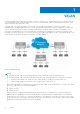
BGP EVPN compared to static VXLAN OS10 supports two types of VXLAN NVO overlay networks: ● Static VXLAN ● BGP EVPN Configure and operate static VXLANs and BGP EVPNs for VXLAN in the same way: ● Manually configure the overlay and underlay networks. ● Manually configure each virtual network and VNI. ● Manually configure access port membership in a virtual network. ● Existing routing protocols provision and learn underlay reachability to VTEP peers.
Figure 3. BGP EVPN topology Leaf nodes Leaf nodes are typically top-of-rack (ToR) switches in a data center network. They act as the VXLAN tunnel endpoints and perform VXLAN encapsulation and decapsulation. Leaf nodes also participate in the MP-BGP EVPN to support control plane and data plane functions. Control plane functions include: ● Initiate and maintain route adjacencies using any routing protocol in the underlay network. ● Advertise locally learned routes to all MP-BGP EVPN peers.
The BGP EVPN running on each VTEP listens to the exchange of route information in the local overlay, encodes the learned routes as BGP EVPN routes, and injects them into BGP to advertise to the peers. Tunnel endpoints advertise as Type 3 EVPN routes. MAC/IP addresses advertise as Type 2 EVPN routes. EVPN instance An EVPN instance (EVI) spans across the VTEPs that participate in an Ethernet VPN. Each virtual-network tenant segment, that is advertised using EVPN, must associate with an EVI.
2. Configure BGP to advertise EVPN routes. 3. Configure EVPN, including the VNI, RD, and RT values associated with the EVPN instance. 4. Verify the BGP EVPN configuration. Configuration 1. Configure BGP to advertise EVPN routes. EVPN requires that you establish MP-BGP sessions between leaf and spine nodes in the underlay network.
d. Send an extended community attribute to the BGP neighbor in ROUTER-BGP-NEIGHBOR mode. send-community extended e. Enable the peer session with the BGP neighbor in ROUTER-BGP-NEIGHBOR mode. no shutdown f. Configure the L2 VPN EVPN address family for VXLAN host-based routing to the BGP peer in ROUTER-BGP-NEIGHBOR mode. address-family l2vpn evpn g. Enable the exchange of L2VPN EVPN addresses with the BGP peer in ROUTER-BGP-NEIGHBOR mode. activate h. Return to ROUTER-BGP mode. exit i.
b. Enable auto-EVI creation for overlay virtual networks in EVPN mode. Auto-EVI creation is supported only if BGP EVPN is used with 2-byte AS numbers and if at least one BGP instance is enabled with the EVPN address family. No further manual configuration is allowed in auto-EVI mode. auto-evi ● Manual EVI configuration mode a. Enable the EVPN control plane in CONFIGURATION mode. evpn b. Manually create an EVPN instance in EVPN mode. The range is from 1 to 65535. evi id c.
Received 311 messages 2 opens, 2 notifications, 3 updates 304 keepalives, 0 route refresh requests Sent 307 messages 4 opens, 0 notifications, 2 updates 301 keepalives, 0 route refresh requests Minimum time between advertisement runs is 30 seconds Minimum time before advertisements start is 0 seconds Capabilities received from neighbor for IPv4 Unicast: MULTIPROTO_EXT(1) ROUTE_REFRESH(2) CISCO_ROUTE_REFRESH(128) 4_OCTET_AS(65) MP_L2VPN_EVPN Capabilities advertised to neighbor for IPv4 Unicast: MULTIPROTO_EX
Dell EMC recommends configuring iBGP peering for the IPv4 address family between the VTEPs in a VLT pair on a dedicated L3 VLAN that is used when connectivity to the underlay L3 network is lost. It is NOT required to enable the EVPN address family on the iBGP peering session between the VTEPs in a VLT pair because EVPN peering to the spine switch is performed on Loopback interfaces. Both VTEPs in a VLT pair advertise identical EVPN routes, which provides redundancy if one of the VTEP peers fails.
VXLAN BGP EVPN routing This section describes how EVPN implements overlay routing between L2 segments associated with EVIs belonging to the same tenant on a VTEP. IETF draft draft-ietf-bess-evpn-inter-subnet-forwarding-05 describes EVPN inter-subnet forwarding, Integrated Routing and Bridging (IRB), and how to use EVPN with IP routing between L2 tenant domains.
overlay network to scale larger than asymmetric routing. Assign the same router MAC address to each VLT peer in a VTEP VLT domain. Each VTEP learns host MAC and MAC-to-IP bindings using ARP snooping for local addresses, and type-2 and type-5 route advertisements from remote VTEPs. In addition to L3 VNI-connected networks, type-5 route advertisements communicate external routes from a border leaf VTEP to all other VTEPs.
Display the EVPN instance configuration OS10# show evpn evi 10000 EVI : 10000, State : up Bridge-Domain : Virtual-Network 10000, VNI 10000 Route-Distinguisher : 1:110.111.170.195:10000(auto) Route-Targets : 0:10000:16787216(auto) both Inclusive Multicast : 110.111.170.107 IRB : Enabled(VRF-TENANT-1) OS10# show evpn evi 20000 EVI : 20000, State : up Bridge-Domain : Virtual-Network 20000, VNI 20000 Route-Distinguisher : 1:110.111.170.
Origin codes: i - IGP, e - EGP, ? - incomplete Network Next Hop Metric LocPrf Weight *>r Route distinguisher: 4.4.4.4:65001 VNI:65001 [5]:[0]:[24]:[11.11.11.0]:[0.0.0.0]/224 4.4.4.4 0 100 32768 *>r Route distinguisher: 3.3.3.3:65002 VNI:65002 [5]:[0]:[24]:[12.12.12.0]:[0.0.0.0]/224 3.3.3.3 0 100 Path ? 0 100 101 ? *>r Route distinguisher: 4.4.4.4:101 VNI:101 [2]:[0]:[48]:[14:18:77:25:6f:4d]:[32]:[11.11.11.2]/224 4.4.4.4 0 100 32768 *>r Route distinguisher: 3.3.3.
Figure 5. VXLAN BGP EVPN use case VTEP 1 Leaf Switch 1. Configure a Loopback interface for the VXLAN underlay using same IP address as the VLT peer. OS10(config)# interface loopback0 OS10(conf-if-lo-0)# no shutdown OS10(conf-if-lo-0)# ip address 192.168.1.1/32 OS10(conf-if-lo-0)# exit 2. Configure the Loopback interface as the VXLAN source tunnel interface.
3. Configure VXLAN virtual networks. OS10(config)# virtual-network 10000 OS10(config-vn-10000)# vxlan-vni 10000 OS10(config-vn-vxlan-vni)# exit OS10(config-vn-10000)# exit OS10(config)# virtual-network 20000 OS10(config-vn-20000)# vxlan-vni 20000 OS10(config-vn-vxlan-vni)# exit OS10(config-vn-20000)# exit 4. Assign VLAN member interfaces to the virtual networks.
OS10(config-router-bgp-100)# address-family ipv4 unicast OS10(config-router-bgp-af)# redistribute connected OS10(config-router-bgp-af)# exit 8. Configure eBGP for the IPv4 point-to-point peering. OS10(config-router-bgp-100)# neighbor 172.16.1.
12. Configure VLT. Configure a dedicated L3 underlay path to reach the VLT Peer in case of a network failure. OS10(config)# interface vlan4000 OS10(config-if-vl-4000)# no shutdown OS10(config-if-vl-4000)# ip address 172.16.250.0/31 OS10(config-if-vl-4000)# exit Configure the VLT port channel.
Configure routing on the virtual networks. OS10(config)# interface OS10(conf-if-vn-10000)# OS10(conf-if-vn-10000)# OS10(conf-if-vn-10000)# OS10(conf-if-vn-10000)# OS10(conf-if-vn-10000)# virtual-network 10000 ip vrf forwarding tenant1 ip address 10.1.0.231/16 ip virtual-router address 10.1.0.
OS10(conf-if-eth1/1/5)# exit OS10(config)# interface port-channel20 OS10(conf-if-po-20)# no shutdown OS10(conf-if-po-20)# switchport mode trunk OS10(conf-if-po-20)# switchport access vlan 200 OS10(conf-if-po-20)# exit OS10(config)# interface OS10(conf-if-eth1/1/6)# OS10(conf-if-eth1/1/6)# OS10(conf-if-eth1/1/6)# OS10(conf-if-eth1/1/6)# ethernet1/1/6 no shutdown channel-group 20 mode active no switchport exit 6. Configure upstream network-facing ports.
OS10(config-router-neighbor)# update-source loopback1 OS10(config-router-neighbor)# no shutdown OS10(config-router-neighbor)# address-family ipv4 unicast OS10(config-router-bgp-neighbor-af)# no activate OS10(config-router-bgp-neighbor-af)# exit OS10(config-router-neighbor)# address-family l2vpn evpn OS10(config-router-bgp-neighbor-af)# activate OS10(config-router-bgp-neighbor-af)# allowas-in 1 OS10(config-router-bgp-neighbor-af)# exit OS10(config-router-neighbor)# exit OS10(config-router-bgp-100)# neighbor
OS10(conf-vlt-1)# vlt-mac aa:bb:cc:dd:ee:ff OS10(conf-vlt-1)# exit Configure UFD with uplink VLT ports and downlink network ports. OS10(config)# uplink-state-group OS10(conf-uplink-state-group-1)# OS10(conf-uplink-state-group-1)# OS10(conf-uplink-state-group-1)# OS10(conf-uplink-state-group-1)# OS10(conf-uplink-state-group-1)# 1 enable downstream ethernet1/1/1-1/1/2 upstream port-channel10 upstream port-channel20 exit Configure iBGP IPv4 peering between VLT peers.
OS10(config-vn-vxlan-vni)# exit OS10(config-vn-10000)# exit OS10(config)# virtual-network 20000 OS10(config-vn-20000)# vxlan-vni 20000 OS10(config-vn-vxlan-vni)# exit OS10(config-vn-20000)# exit 4. Configure unused VLAN ID for untagged membership. OS10(config)# virtual-network untagged-vlan 1000 5. Configure access ports as VLAN members for a port-scoped VLAN-to-VNI mapping.
OS10(configure-router-bgp-af)# redistribute connected OS10(configure-router-bgp-af)# exit 9. Configure eBGP for the IPv4 point-to-point peering. OS10(config-router-bgp-100)# neighbor 172.18.1.1 OS10(config-router-neighbor)# remote-as 101 OS10(config-router-neighbor)# address-family ipv4 unicast OS10(config-router-bgp-neighbor-af)# allowas-in 1 OS10(config-router-bgp-neighbor-af)# exit OS10(config-router-neighbor)# no shutdown OS10(config-router-neighbor)# exit OS10(config-router-bgp-100)# neighbor 172.18.2.
OS10(config-evpn-evi-10000)# route-target auto OS10(config-evpn-evi-10000)# exit OS10(config-evpn)# evi 20000 OS10(config-evpn-evi-20000)# OS10(config-evpn-evi-20000)# OS10(config-evpn-evi-20000)# OS10(config-evpn-evi-20000)# OS10(config-evpn)# exit vni 20000 rd auto route-target auto exit 13. Configure VLT. Configure a VLTi VLAN for the virtual network.
Configure iBGP IPv4 peering between VLT peers. OS10(config)# router bgp 100 OS10(config-router-bgp-100)# neighbor 172.16.250.11 OS10(config-router-neighbor)# remote-as 100 OS10(config-router-neighbor)# no shutdown OS10(config-router-neighbor)# exit OS10(config-router-bgp-100)# exit 14. Configure IP routing in the overlay network. Create the tenant VRF. OS10(config)# ip vrf tenant1 OS10(conf-vrf)# exit Configure an anycast gateway MAC address.
5. Configure access ports as VLAN members for a port-scoped VLAN-to-VNI mapping.
OS10(config-router-neighbor)# remote-as 101 OS10(config-router-neighbor)# address-family ipv4 unicast OS10(config-router-bgp-neighbor-af)# allowas-in 1 OS10(config-router-bgp-neighbor-af)# exit OS10(config-router-neighbor)# no shutdown OS10(config-router-neighbor)# exit OS10(config-router-bgp-100)# exit 10. Configure a Loopback interface for BGP EVPN peering different from the VLT peer IP address. OS10(config)# interface loopback1 OS10(conf-if-lo-1)# no shutdown OS10(conf-if-lo-1)# ip address 172.19.0.
Configure a VLTi VLAN for the virtual network. OS10(config)# virtual-network 10000 OS10(config-vn-10000)# vlti-vlan 100 OS10(config-vn-10000)# exit OS10(config)# virtual-network 20000 OS10(conf-vn-20000)# vlti-vlan 200 OS10(conf-vn-20000)# exit Configure a dedicated L3 underlay path to reach the VLT Peer in case of a network failure. OS10(config)# interface vlan4000 OS10(config-if-vl-4000)# no shutdown OS10(config-if-vl-4000)# ip address 172.16.250.
Create a tenant VRF. OS10(config)# ip vrf tenant1 OS10(conf-vrf)# exit Configure an anycast gateway MAC address. OS10(config)# ip virtual-router mac-address 00:01:01:01:01:01 Configure routing on the virtual networks. OS10(config)# interface OS10(conf-if-vn-10000)# OS10(conf-if-vn-10000)# OS10(conf-if-vn-10000)# OS10(conf-if-vn-10000)# OS10(conf-if-vn-10000)# virtual-network 10000 ip vrf forwarding tenant1 ip address 10.1.0.234/16 ip virtual-router address 10.1.0.
OS10(conf-router-bgp-101)# neighbor 172.17.1.0 OS10(conf-router-neighbor)# remote-as 100 OS10(conf-router-neighbor)# no shutdown OS10(conf-router-neighbor)# address-family ipv4 unicast OS10(conf-router-neighbor-af)# no sender-side-loop-detection OS10(conf-router-neighbor-af)# exit OS10(conf-router-neighbor)# exit OS10(conf-router-bgp-101)# neighbor 172.18.1.
OS10(conf-router-neighbor)# address-family l2vpn evpn OS10(conf-router-neighbor-af)# no sender-side-loop-detection OS10(conf-router-neighbor-af)# activate OS10(conf-router-neighbor-af)# exit OS10(conf-router-bgp-101)# neighbor 172.19.0.
OS10(conf-router-bgp-101)# neighbor 172.18.2.0 OS10(conf-router-neighbor)# remote-as 100 OS10(conf-router-neighbor)# no shutdown OS10(conf-router-neighbor)# address-family ipv4 unicast OS10(conf-router-neighbor-af)# no sender-side-loop-detection OS10(conf-router-neighbor-af)# exit OS10(conf-router-neighbor)# exit OS10(conf-router-bgp-101)# neighbor 172.19.2.
OS10(conf-router-neighbor)# remote-as 100 OS10(conf-router-neighbor)# send-community extended OS10(conf-router-neighbor)# update-source loopback1 OS10(conf-router-neighbor)# no shutdown OS10(conf-router-neighbor)# address-family ipv4 unicast OS10(conf-router-neighbor-af)# no activate OS10(conf-router-neighbor-af)# exit OS10(conf-router-neighbor)# address-family l2vpn evpn OS10(conf-router-neighbor-af)# no sender-side-loop-detection OS10(conf-router-neighbor-af)# activate OS10(conf-router-neighbor-af)# exit
64 bytes from 10.2.0.10: icmp_seq=4 ttl=63 time=0.944 ms 64 bytes from 10.2.0.10: icmp_seq=5 ttl=63 time=0.806 ms --- 10.2.0.10 ping statistics --5 packets transmitted, 5 received, 0% packet loss, time 4078ms rtt min/avg/max/mdev = 0.806/0.851/0.944/0.051 ms root@HOST-A:~# 5. Check connectivity between host A and host C. root@HOST-A:~# ping 10.1.0.20 -c 5 PING 10.1.0.20 (10.1.0.20) 56(84) bytes of 64 bytes from 10.1.0.20: icmp_seq=1 ttl=64 64 bytes from 10.1.0.20: icmp_seq=2 ttl=64 64 bytes from 10.1.0.
Figure 6. VXLAN BGP EVPN with multiple AS VTEP 1 Leaf Switch 1. Configure a Loopback interface for the VXLAN underlay using same IP address as the VLT peer. OS10(config)# interface loopback0 OS10(conf-if-lo-0)# no shutdown OS10(conf-if-lo-0)# ip address 192.168.1.1/32 OS10(conf-if-lo-0)# exit 2. Configure the Loopback interface as the VXLAN source tunnel interface.
3. Configure VXLAN virtual networks. OS10(config)# virtual-network 10000 OS10(config-vn-10000)# vxlan-vni 10000 OS10(config-vn-vxlan-vni)# exit OS10(config-vn-10000)# exit OS10(config)# virtual-network 20000 OS10(config-vn-20000)# vxlan-vni 20000 OS10(config-vn-vxlan-vni)# exit OS10(config-vn-20000)# exit 4. Assign VLAN member interfaces to the virtual networks.
OS10(config-router-bgp-99)# address-family ipv4 unicast OS10(config-router-bgp-af)# redistribute connected OS10(config-router-bgp-af)# exit 8. Configure eBGP for the IPv4 point-to-point peering. OS10(config-router-bgp-99)# neighbor 172.16.1.1 OS10(config-router-neighbor)# remote-as 101 OS10(config-router-neighbor)# no shutdown OS10(config-router-neighbor)# exit OS10(config-router-bgp-99)# neighbor 172.16.2.
OS10(config-evpn-evi-20000)# route-target 100:20000 import OS10(config-evpn-evi-20000)#exit OS10(config-evpn)# 12. Configure VLT. Configure a dedicated L3 underlay path to reach the VLT Peer in case of a network failure. OS10(config)# interface vlan4000 OS10(config-if-vl-4000)# no shutdown OS10(config-if-vl-4000)# ip address 172.16.250.0/31 OS10(config-if-vl-4000)# exit Configure the VLT port channel.
Configure an anycast gateway MAC address. OS10(config)# ip virtual-router mac-address 00:01:01:01:01:01 Configure routing on the virtual networks. OS10(config)# interface OS10(conf-if-vn-10000)# OS10(conf-if-vn-10000)# OS10(conf-if-vn-10000)# OS10(conf-if-vn-10000)# OS10(conf-if-vn-10000)# virtual-network10000 ip vrf forwarding tenant1 ip address 10.1.0.231/16 ip virtual-router address 10.1.0.
OS10(config)# interface OS10(conf-if-eth1/1/5)# OS10(conf-if-eth1/1/5)# OS10(conf-if-eth1/1/5)# OS10(conf-if-eth1/1/5)# ethernet1/1/5 no shutdown channel-group 10 mode active no switchport exit OS10(config)# interface port-channel20 OS10(conf-if-po-20)# no shutdown OS10(conf-if-po-20)# switchport mode trunk OS10(conf-if-po-20)# switchport access vlan 200 OS10(conf-if-po-20)# exit OS10(config)# interface OS10(conf-if-eth1/1/6)# OS10(conf-if-eth1/1/6)# OS10(conf-if-eth1/1/6)# OS10(conf-if-eth1/1/6)# ethern
OS10(config-router-neighbor)# address-family ipv4 unicast OS10(config-router-bgp-neighbor-af)# no activate OS10(config-router-bgp-neighbor-af)# exit OS10(config-router-neighbor)# address-family l2vpn evpn OS10(config-router-bgp-neighbor-af)# activate OS10(config-router-bgp-neighbor-af)# exit OS10(config-router-neighbor)# exit OS10(config-router-bgp-99)# neighbor 172.202.0.
OS10(conf-if-eth1/1/4)# no switchport OS10(conf-if-eth1/1/4)# exit Configure the VLT domain. OS10(config)# vlt-domain 1 OS10(conf-vlt-1)# backup destination 10.16.150.2 OS10(conf-vlt-1)# discovery-interface ethernet1/1/3,1/1/4 OS10(conf-vlt-1)# vlt-mac aa:bb:cc:dd:ee:ff OS10(conf-vlt-1)# exit Configure UFD with uplink VLT ports and downlink network ports.
2. Configure the Loopback interface as the VXLAN source tunnel interface. OS10(config)# nve OS10(config-nve)# source-interface loopback0 OS10(config-nve)# exit 3. Configure VXLAN virtual networks. OS10(config)# virtual-network 10000 OS10(config-vn-10000)# vxlan-vni 10000 OS10(config-vn-vxlan-vni)# exit OS10(config-vn-10000)# exit OS10(config)# virtual-network 20000 OS10(config-vn-20000)# vxlan-vni 20000 OS10(config-vn-vxlan-vni)# exit OS10(config-vn-20000)# exit 4.
OS10(conf-if-eth1/1/1)# mtu 1650 OS10(conf-if-eth1/1/2)# ip address 172.18.2.0/31 OS10(conf-if-eth1/1/2)# exit 8. Configure eBGP. OS10(config)# router bgp 100 OS10(config-router-bgp-100)# router-id 172.18.0.1 OS10(config-router-bgp-100)# address-family ipv4 unicast OS10(configure-router-bgp-af)# redistribute connected OS10(configure-router-bgp-af)# exit 9. Configure eBGP for the IPv4 point-to-point peering. OS10(config-router-bgp-100)# neighbor 172.18.1.
OS10(config-evpn-evi-10000)# rd 192.168.2.1:10000 OS10(config-evpn-evi-10000)# route-target 99:10000 import OS10(config-evpn-evi-10000)# route-target 100:10000 both OS10(config-evpn-evi-10000)#exit OS10(config-evpn)# evi 20000 OS10(config-evpn-evi-20000)# vni 20000 OS10(config-evpn-evi-20000)# rd 192.168.2.1:20000 OS10(config-evpn-evi-20000)# route-target 99:20000 import OS10(config-evpn-evi-20000)# route-target 100:20000 both OS10(config-evpn-evi-20000)#exit OS10(config-evpn)# 13. Configure VLT.
Configure iBGP IPv4 peering between VLT peers. OS10(config)# router bgp 100 OS10(config-router-bgp-100)# neighbor 172.16.250.11 OS10(config-router-neighbor)# remote-as 100 OS10(config-router-neighbor)# no shutdown OS10(config-router-neighbor)# exit OS10(config-router-bgp-100)# exit 14. Configure IP routing in the overlay network. Create the tenant VRF. OS10(config)# ip vrf tenant1 OS10(conf-vrf)# exit Configure an anycast gateway MAC address.
5. Configure access ports as VLAN members for a port-scoped VLAN-to-VNI mapping.
OS10(config-router-neighbor)# exit OS10(config-router-bgp-100)# exit 10. Configure a Loopback interface for BGP EVPN peering different from the VLT peer IP address. OS10(config)# interface loopback1 OS10(conf-if-lo-1)# no shutdown OS10(conf-if-lo-1)# ip address 172.19.0.1/32 OS10(conf-if-lo-1)# exit 11. Configure BGP EVPN peering. OS10(config)# router bgp 100 OS10(config-router-bgp-100)# neighbor 172.201.0.
OS10(conf-vn-20000)# vlti-vlan 200 OS10(conf-vn-20000)# exit Configure a dedicated L3 underlay path to reach the VLT Peer in case of a network failure. OS10(config)# interface vlan4000 OS10(config-if-vl-4000)# no shutdown OS10(config-if-vl-4000)# ip address 172.16.250.11/31 OS10(config-if-vl-4000)# exit Configure VLT port channels.
Configure routing on the virtual networks. OS10(config)# interface OS10(conf-if-vn-10000)# OS10(conf-if-vn-10000)# OS10(conf-if-vn-10000)# OS10(conf-if-vn-10000)# OS10(conf-if-vn-10000)# virtual-network10000 ip vrf forwarding tenant1 ip address 10.1.0.234/16 ip virtual-router address 10.1.0.
OS10(conf-router-neighbor)# exit OS10(conf-router-bgp-101)# exit 4. Configure a Loopback interface for BGP EVPN peering. OS10(config)# interface loopback1 OS10(conf-if-lo-1)# no shutdown OS10(conf-if-lo-1)# ip address 172.201.0.1/32 OS10(conf-if-lo-1)# exit 5. Configure BGP EVPN peer sessions. OS10(config)# router bgp 101 OS10(conf-router-bgp-101)# neighbor 172.16.0.
Spine Switch 2 1. Configure downstream ports on the underlay links to the leaf switches.
OS10(conf-router-neighbor)# update-source loopback1 OS10(conf-router-neighbor)# no shutdown OS10(conf-router-neighbor)# address-family ipv4 unicast OS10(conf-router-neighbor-af)# no activate OS10(conf-router-neighbor-af)# exit OS10(conf-router-neighbor)# address-family l2vpn evpn OS10(conf-router-neighbor-af)# activate OS10(conf-router-neighbor-af)# exit OS10(conf-router-bgp-102)# neighbor 172.17.0.
2. Verify EVPN configurations and EVPN parameters. LEAF1# show evpn evi EVI : 10000, State : up Bridge-Domain : Route-Distinguisher : Route-Targets : Inclusive Multicast : IRB : EVI : 20000, State : up Bridge-Domain : Route-Distinguisher : Route-Targets : Inclusive Multicast : IRB : LEAF1# Virtual-Network 10000, VNI 10000 1:192.168.1.1:10000 0:99:10000 both, 0:100:10000 import 192.168.2.1 Enabled(tenant1) Virtual-Network 20000, VNI 20000 1:192.168.1.1:20000 0:99:10000 both, 0:100:10000 import 192.168.2.
rtt min/avg/max/mdev = 0.640/0.669/0.707/0.041 ms root@HOST-A:~# NOTE: Follow Steps 1 to 6 to check ping connectivity between combinations of other hosts, and between hosts through different virtual-network IP addresses. Example: VXLAN BGP EVPN — Centralized L3 gateway The following VXLAN with BGP EVPN example uses a centralized Layer 3 gateway to perform virtual-network routing. It is based on the sample configuration in Example: VXLAN BGP EVPN — Multiple AS topology.
Figure 7. VXLAN BGP EVPN with centralized L3 gateway NOTE: This centralized L3 gateway example for VXLAN BGP EVPN uses the same configuration steps as in Example: VXLAN BGP EVPN — Multiple AS topology. Configure each spine and leaf switch as in the Multiple AS topology example, except: ● Because VTEPs 1 and 2 operate only in Layer 2 VXLAN mode, do not configure IP switching in the overlay network.
Create a tenant VRF. OS10(config)# ip vrf tenant1 OS10(conf-vrf)# exit Configure an anycast gateway MAC address. OS10(config)# ip virtual-router mac-address 00:01:01:01:01:01 Configure routing on the virtual networks. OS10(config)# interface OS10(conf-if-vn-10000)# OS10(conf-if-vn-10000)# OS10(conf-if-vn-10000)# OS10(conf-if-vn-10000)# OS10(conf-if-vn-10000)# virtual-network10000 ip vrf forwarding tenant1 ip address 10.1.0.233/16 ip virtual-router address 10.1.0.
S4048T-ON, S6010-ON, and the S4100-ON series, routing after decapsulation is performed only between virtual networks. You can connect an egress virtual network to a VLAN in an external router, which connects to the external network. In the following example, VLT domain 1 is a VLT VTEP. VLT domain 2 is the border leaf VLT VTEP pair. All virtual networks in the data center network are configured in all VTEPs with virtual-network IP and anycast IP gateway addresses.
Figure 8. VXLAN BGP EVPN with border leaf gateway NOTE: This border leaf gateway example for VXLAN BGP EVPN uses the same configuration steps as in Example: VXLAN BGP EVPN — Multiple AS topology. Configure each spine and leaf switch as in the Multiple AS topology example and add the following additional configuration steps on each VTEP. VTEP 1 Leaf Switch 1. Configure a dedicated VXLAN virtual network.
2. Configure routing on the virtual network. OS10(config)# interface virtual-network 500 OS10(conf-if-vn-10000)# ip vrf forwarding tenant1 OS10(conf-if-vn-10000)# ip address 10.5.0.231/16 3. Configure a static route for outbound traffic sent to the anycast MAC address of the dedicated virtual network. OS10(config)#ip route 0.0.0.0/0 10.5.0.100 VTEP 2 Leaf Switch 1. Configure a dedicated VXLAN virtual network.
5. Configure a static route for outbound traffic sent to VLAN 200. OS10(config)#ip route 0.0.0.0/0 10.10.0.3 VTEP 4 Leaf Switch 1. Configure a dedicated VXLAN virtual network. OS10(config)# virtual-network 500 OS10(config-vn-500)# vxlan-vni 500 OS10(config-vn-vxlan-vni)# exit OS10(config-vn-10000)# exit 2. Configure an anycast gateway MAC address on the boder leaf VTEP. This MAC address must be different from the anycast gateway MAC address configured on non-border-leaf VTEPs.
VTEP 1 Leaf Switch 1. Configure a Loopback interface for the VXLAN underlay using same IP address as the VLT peer. OS10(config)# interface loopback0 OS10(conf-if-lo-0)# no shutdown OS10(conf-if-lo-0)# ip address 192.168.1.1/32 OS10(conf-if-lo-0)# exit 2. Configure the Loopback interface as the VXLAN source tunnel interface.
3. Configure the VXLAN virtual network. OS10(config)# virtual-network 10000 OS10(config-vn-10000)# vxlan-vni 10000 OS10(config-vn-vxlan-vni)# exit OS10(config-vn-10000)# exit 4. Assign VLAN member interfaces to the virtual network. Use a switch-scoped VLAN-to-VNI mapping: OS10(config)# interface OS10(config-if-vl-100)# OS10(config-if-vl-100)# OS10(config-if-vl-100)# vlan100 virtual-network 10000 no shutdown exit 5. Configure access ports as VLAN members for a switch-scoped VLAN-to-VNI mapping.
OS10(config-router-neighbor)# exit OS10(config-router-bgp-100)# exit 9. Configure a Loopback interface for BGP EVPN peering different from the VLT peer IP address. OS10(config)# interface loopback1 OS10(conf-if-lo-1)# no shutdown OS10(conf-if-lo-1)# ip address 172.16.0.1/32 OS10(conf-if-lo-1)# exit 10. Configure BGP EVPN peering. OS10(config)# router bgp 100 OS10(config-router-bgp-100)# neighbor 172.201.0.
OS10(conf-if-eth1/1/3)# no switchport OS10(conf-if-eth1/1/3)# exit OS10(config)# interface OS10(conf-if-eth1/1/4)# OS10(conf-if-eth1/1/4)# OS10(conf-if-eth1/1/4)# ethernet1/1/4 no shutdown no switchport exit Configure the VLT domain. OS10(config)# vlt-domain 1 OS10(conf-vlt-1)# backup destination 10.16.150.1 OS10(conf-vlt-1)# discovery-interface ethernet1/1/3,1/1/4 OS10(conf-vlt-1)# vlt-mac aa:bb:cc:dd:ee:ff OS10(conf-vlt-1)# exit Configure UFD with uplink VLT ports and downlink network ports.
15. Configure advertisement of connected networks through EVPN type-5 routes. OS10(config)# evpn OS10(config-evpn)# vrf tenant1 OS10(config-evpn-vrf-tenant1)# advertise ipv4 connected OS10(config-evpn-vrf-tenant1)# exit VTEP 2 Leaf Switch 1. Configure a Loopback interface for the VXLAN underlay using the same IP address as the VLT peer. OS10(config)# interface loopback0 OS10(conf-if-lo-0)# no shutdown OS10(conf-if-lo-0)# ip address 192.168.1.1/32 OS10(conf-if-lo-0)# exit 2.
OS10(conf-if-eth1/1/2)# ip address 172.17.2.0/31 OS10(conf-if-eth1/1/2)# exit 7. Configure eBGP. OS10(config)# router bgp 100 OS10(config-router-bgp-100)# router-id 172.17.0.1 OS10(config-router-bgp-100)# address-family ipv4 unicast OS10(configure-router-bgp-af)# redistribute connected OS10(configure-router-bgp-af)# exit 8. Configure eBGP for the IPv4 point-to-point peering. OS10(config-router-bgp-100)# neighbor 172.17.1.
11. Configure EVPN for the VXLAN virtual network. Configure the EVPN instance, RD, and RT using auto-EVI mode. OS10(config)# evpn OS10(config-evpn)# auto-evi OS10(config-evpn)# exit 12. Configure VLT. Configure a dedicated L3 underlay path to reach the VLT Peer in case of a network failure. OS10(config)# interface vlan4000 OS10(config-if-vl-4000)# no shutdown OS10(config-if-vl-4000)# ip address 172.16.250.1/31 OS10(config-if-vl-4000)# exit Configure the VLT port channel.
Configure an anycast gateway MAC address. OS10(config)# ip virtual-router mac-address 00:01:01:01:01:01 Configure routing on the virtual network. OS10(config)# interface OS10(conf-if-vn-10000)# OS10(conf-if-vn-10000)# OS10(conf-if-vn-10000)# OS10(conf-if-vn-10000)# OS10(conf-if-vn-10000)# virtual-network 10000 ip vrf forwarding tenant1 ip address 10.1.0.232/16 ip virtual-router address 10.1.0.100 no shutdown exit 14. Configure symmetric IRB.
OS10(config)# interface OS10(conf-if-eth1/1/6)# OS10(conf-if-eth1/1/6)# OS10(conf-if-eth1/1/6)# OS10(conf-if-eth1/1/6)# ethernet1/1/6 no shutdown channel-group 20 mode active no switchport exit 6. Add the access ports to the virtual network. OS10(config)# virtual-network 20000 OS10(config-vn-20000)# member-interface port-channel 20 untagged OS10(config-vn-20000)# exit 7. Configure upstream network-facing ports.
OS10(config-router-neighbor)# update-source loopback1 OS10(config-router-neighbor)# no shutdown OS10(config-router-neighbor)# address-family ipv4 unicast OS10(config-router-bgp-neighbor-af)# no activate OS10(config-router-bgp-neighbor-af)# exit OS10(config-router-neighbor)# address-family l2vpn evpn OS10(config-router-bgp-neighbor-af)# activate OS10(config-router-bgp-neighbor-af)# allowas-in 1 OS10(config-router-bgp-neighbor-af)# exit OS10(config-router-neighbor)# exit OS10(config-router-bgp-100)# neighbor
Configure the VLT domain. OS10(config)# vlt-domain 1 OS10(conf-vlt-1)# backup destination 10.16.150.3 OS10(conf-vlt-1)# discovery-interface ethernet1/1/3,1/1/4 OS10(conf-vlt-1)# vlt-mac aa:bb:cc:dd:ff:ee OS10(conf-vlt-1)# exit Configure UFD with uplink VLT ports and downlink network ports.
OS10(conf-if-eth1/1/7)# switchport mode trunk OS10(conf-if-eth1/1/7)# switchport trunk allowed vlan 200 17. Configure advertisement of the connected networks via EVPN Type-5 routes. OS10(config)# evpn OS10(config-evpn)# vrf tenant1 OS10(config-evpn-vrf-tenant1)# advertise ipv4 connected OS10(config-evpn-vrf-tenant1)# exit 18. Configure BGP session with external router on the border-leaf VTEPs. OS10(config)# router bgp 100 OS10(config-router-bgp-100)# vrf tenant1 OS10(config-router-bgp-100-vrf)# neighbor 10.
VTEP 4 Leaf Switch 1. Configure a Loopback interface for the VXLAN underlay using same IP address as the VLT peer. OS10(config)# interface loopback0 OS10(conf-if-lo-0)# no shutdown OS10(conf-if-lo-0)# ip address 192.168.2.1/32 OS10(conf-if-lo-0)# exit 2. Configure the Loopback interface as the VXLAN source tunnel interface. OS10(config)# nve OS10(config-nve)# source-interface loopback0 OS10(config-nve)# exit 3. Configure the VXLAN virtual network.
OS10(configure-router-bgp-af)# redistribute connected OS10(configure-router-bgp-af)# exit 9. Configure eBGP for the IPv4 point-to-point peering. OS10(config-router-bgp-100)# neighbor 172.19.1.1 OS10(config-router-neighbor)# remote-as 101 OS10(config-router-neighbor)# address-family ipv4 unicast OS10(config-router-bgp-neighbor-af)# allowas-in 1 OS10(config-router-bgp-neighbor-af)# exit OS10(config-router-neighbor)# no shutdown OS10(config-router-neighbor)# exit OS10(config-router-bgp-100)# neighbor 172.19.2.
OS10(config-evpn-evi-20000)# route-target auto OS10(config-evpn-evi-20000)# exit OS10(config-evpn)# exit 13. Configure VLT. Configure a VLTi VLAN for the virtual network. OS10(config)# virtual-network 20000 OS10(conf-vn-20000)# vlti-vlan 200 OS10(conf-vn-20000)# exit Configure a dedicated L3 underlay path to reach the VLT Peer in case of a network failure. OS10(config)# interface vlan4000 OS10(config-if-vl-4000)# no shutdown OS10(config-if-vl-4000)# ip address 172.16.250.
Configure an anycast gateway MAC address. OS10(config)# ip virtual-router mac-address 00:01:01:01:01:01 Configure routing on the virtual network. OS10(config)# interface OS10(conf-if-vn-20000)# OS10(conf-if-vn-20000)# OS10(conf-if-vn-20000)# OS10(conf-if-vn-20000)# OS10(conf-if-vn-20000)# virtual-network 20000 ip vrf forwarding tenant1 ip address 10.2.0.234/16 ip virtual-router address 10.2.0.100 no shutdown exit 15. Configure symmetric IRB.
With connected routes of virtual networks present in an individual VTEP advertised as type-5 routes, the border-leaf router has information about all the virtual networks present in the pod.
3. Configure eBGP IPv4 peer sessions on the P2P links. OS10(conf-router-bgp-101)# neighbor 172.16.1.0 OS10(conf-router-neighbor)# remote-as 100 OS10(conf-router-neighbor)# no shutdown OS10(conf-router-neighbor)# address-family ipv4 unicast OS10(conf-router-neighbor-af)# no sender-side-loop-detection OS10(conf-router-neighbor-af)# exit OS10(conf-router-neighbor)# exit OS10(conf-router-bgp-101)# neighbor 172.17.1.
OS10(conf-router-bgp-101)# neighbor 172.18.0.
OS10(conf-router-neighbor-af)# exit OS10(conf-router-neighbor)# exit OS10(conf-router-bgp-101)# neighbor 172.17.2.0 OS10(conf-router-neighbor)# remote-as 100 OS10(conf-router-neighbor)# no shutdown OS10(conf-router-neighbor)# address-family ipv4 unicast OS10(conf-router-neighbor-af)# no sender-side-loop-detection OS10(conf-router-neighbor-af)# exit OS10(conf-router-neighbor)# exit OS10(conf-router-bgp-101)# neighbor 172.18.2.
OS10(conf-router-neighbor)# address-family ipv4 unicast OS10(conf-router-neighbor-af)# no activate OS10(conf-router-neighbor-af)# exit OS10(conf-router-neighbor)# address-family l2vpn evpn OS10(conf-router-neighbor-af)# no sender-side-loop-detection OS10(conf-router-neighbor-af)# activate OS10(conf-router-neighbor-af)# exit OS10(conf-router-bgp-101)# neighbor 172.19.0.
4. Check connectivity between host A and host B. root@HOST-A:~# ping 10.2.0.20 -c 5 PING 10.2.0.10 (10.2.0.10) 56(84) bytes of 64 bytes from 10.2.0.10: icmp_seq=1 ttl=63 64 bytes from 10.2.0.10: icmp_seq=2 ttl=63 64 bytes from 10.2.0.10: icmp_seq=3 ttl=63 64 bytes from 10.2.0.10: icmp_seq=4 ttl=63 64 bytes from 10.2.0.10: icmp_seq=5 ttl=63 data. time=0.824 time=0.847 time=0.835 time=0.944 time=0.806 ms ms ms ms ms --- 10.2.0.
Example - VXLAN BGP EVPN symmetric IRB with unnumbered BGP peering The following BGP EVPN example uses a Clos leaf-spine topology with BGP over unnumbered interfaces. The following explains how the network is configured: ● External BGP (eBGP) over unnumbered interfaces is used to exchange both IPv4 routes and EVPN routes. ● You need not configure IP addresses on links that connect Spine and Leaf switches. BGP Unnumbered peering works without an IP address configuration on Spine-Leaf links.
● On leaf switches 1 and 2, access ports are assigned to a virtual network using a switch-scoped VLAN. EVPN for the overlay VXLAN is configured using auto-EVI mode. ● On leaf switches 3 and 4, access ports are assigned to a virtual network using a port-scoped VLAN. EVPN for the overlay VXLAN is configured using manual EVI mode with RT and RD values configured in auto mode.
OS10(config-router-neighbor)# inherit template ebgp_unified inherit-type ebgp OS10(config-router-neighbor)# no shutdown OS10(config-router-neighbor)# exit OS10(config-router-bgp-101)# neighbor interface ethernet1/1/4 OS10(config-router-neighbor)# inherit template ebgp_unified inherit-type ebgp OS10(config-router-neighbor)# no shutdown OS10(config-router-neighbor)# exit Spine Switch 2 configuration 1. Configure downstream ports as unnumbered interfaces.
OS10(config-router-neighbor)# inherit template ebgp_unified inherit-type ebgp OS10(config-router-neighbor)# no shutdown OS10(config-router-neighbor)# exit VTEP Leaf Switch 1 configuration 1. Configure a loopback interface for the VXLAN underlay using the same IP address as the VLT peer. OS10(config)# interface loopback0 OS10(conf-if-lo-0)# no shutdown OS10(conf-if-lo-0)# ip address 192.168.1.1/32 OS10(conf-if-lo-0)# exit 2. Configure the loopback interface as the VXLAN source tunnel interface.
OS10(config-router-bgp-af)# redistribute connected OS10(config-router-bgp-af)# exit 8. Configure a BGP unnumbered neighbor over network facing ports. Use a template to simplify the configuration on multiple interfaces. These neighbors are configured to carry IPv4 address family (default) and L2VPN EVPN address family.
● Configure UFD with uplink VLT ports and downlink network ports. OS10(config)# uplink-state-group OS10(conf-uplink-state-group-1)# OS10(conf-uplink-state-group-1)# OS10(conf-uplink-state-group-1)# OS10(conf-uplink-state-group-1)# 1 enable downstream ethernet1/1/1-1/1/2 upstream port-channel10 exit ● Configure iBGP unnumbered peering between VLT peers with both IPv4 and L2VPN EVPN address families.
2. Configure the loopback interface as the VXLAN source tunnel interface. OS10(config)# nve OS10(config-nve)# source-interface loopback0 OS10(config-nve)# exit 3. Configure the VXLAN virtual network. OS10(config)# virtual-network 10000 OS10(config-vn-10000)# vxlan-vni 10000 OS10(config-vn-vxlan-vni)# exit OS10(config-vn)# exit 4. Assign VLAN member interfaces to the virtual network. Use a switch-scoped VLAN-to-VNI mapping.
OS10(config-router-bgp-201)# neighbor interface ethernet1/1/2 OS10(config-router-neighbor)# inherit template ebgp_unified inherit-type ebgp OS10(config-router-neighbor)# no shutdown OS10(config-router-neighbor)# exit 9. Configure EVPN for the VXLAN virtual network. Configure the EVPN instances using Auto EVI mode and Disable ASN in the generated RT.
OS10(config-router-neighbor)# no shutdown OS10(config-router-neighbor)# exit 11. Configure IP routing in overlay network. ● Create a tenant VRF. OS10(config)# ip vrf tenant1 OS10(conf-vrf)# exit ● Configure an anycast gateway MAC address. OS10(config)# ip virtual-router mac-address 00:01:01:01:01:01 ● Configure routing on the virtual network.
OS10(conf-if-po-20)# switchport mode trunk OS10(conf-if-po-20)# no switchport access vlan OS10(conf-if-po-20)# exit OS10(config)# interface ethernet1/1/6 OS10(conf-if-eth1/1/6)# no shutdown OS10(conf-if-eth1/1/6)# channel-group 20 mode active OS10(conf-if-eth1/1/6)# exit 6. Add the access ports to the virtual network. OS10(config)# virtual-network 20000 OS10(config-vn-20000)# member-interface port-channel 20 untagged OS10(config-vn-20000)# exit 7.
NOTE: Use the disable-rt-asn command to autoderive RT that does not include the ASN in the RT value. This allows auto RT to be used even if the Clos leaf-spine design has separate ASN for each leaf node. Configure this command only when all the VTEPs are OS10 switches. 11. Configure VLT. ● Configure a VLTi VLAN for the virtual network.
● Create the tenant VRF. OS10(config)# ip vrf tenant1 OS10(conf-vrf)# exit ● Configure an anycast gateway MAC address. OS10(config)# ip virtual-router mac-address 00:01:01:01:01:01 ● Configure routing on the virtual network. OS10(config)# interface OS10(conf-if-vn-20000)# OS10(conf-if-vn-20000)# OS10(conf-if-vn-20000)# OS10(conf-if-vn-20000)# OS10(conf-if-vn-20000)# virtual-network 20000 ip vrf forwarding tenant1 ip address 10.2.0.233/16 ip virtual-router address 10.2.0.100 no shutdown exit 13.
4. Configure an unused VLAN ID for untagged membership. OS10(config)# virtual-network untagged-vlan 1000 5. Configure access ports as VLAN members for a port-scoped VLAN-to-VNI mapping.
OS10(config-evpn)# evi 20000 OS10(config-evpn-evi-20000)# OS10(config-evpn-evi-20000)# OS10(config-evpn-evi-20000)# OS10(config-evpn-evi-20000)# OS10(config-evpn)# exit vni 20000 rd auto route-target auto exit NOTE: Use the disable-rt-asn command to autoderive RT that does not include the ASN in the RT value. This allows auto RT to be used even if the Clos leaf-spine design has separate ASN for each leaf node. Configure this command only when all the VTEPs are OS10 switches. 11. Configure VLT.
OS10(config-router-neighbor)# no shutdown OS10(config-router-neighbor)# exit 12. Configure IP routing in the overlay network. ● Create a tenant VRF. OS10(config)# ip vrf tenant1 OS10(conf-vrf)# exit ● Configure an anycast gateway MAC address. OS10(config)# ip virtual-router mac-address 00:01:01:01:01:01 ● Configure routing on the virtual network.
Example - Route leaking across VRFs in a VXLAN BGP EVPN symmetric IRB topology The following VXLAN with BGP EVPN example uses a Clos leaf-spine topology to show how to set up route leaking across VRF in a symmetric IRB topology. The following explains how the network is configured: ● All VTEPs perform symmetric IRB routing. In this example, all spine nodes are in one autonomous system and each VTEP in the leaf network belongs to a different autonomous system. Spine switch 1 is in AS 101.
● Route leaking is done between: ○ VRF-Yellow and VRF-Green. ○ VRF-Yellow and VRF-Red. ○ VRF-Yellow and VRF-default (underlay with external router) NOTE: Route leaking is not performed between VRF-Green and VRF-Red. ● On VTEPs 1 and 2, two VRFs are present – VRF-Yellow and VRF-Green. VN10001 is part of VRF-Yellow and VN20001 is part of VRF-Green. ● On VTEPs 3 and 4, three VRFs are present – VRF-Yellow, VRF-Green and VRF-Red. VN10001 is part of VRF-Yellow and VN30001 is part of VRF-Red.
OS10(conf-if-vn-10001)# OS10(conf-if-vn-10001)# OS10(conf-if-vn-10001)# OS10(config)# interface OS10(conf-if-vn-20001)# OS10(conf-if-vn-20001)# OS10(conf-if-vn-20001)# ip address 10.1.0.2/24 ip virtual-router address 10.1.0.254 virtual-network 20001 ip vrf forwarding Green ip address 10.2.0.2/24 ip virtual-router address 10.2.0.254 3. Configure EVPN with IP-VRFs.
4. Configure the border-leaf to advertise the default route into the EVPN in each VRF. From the other VTEPs, any traffic to an external network and also to networks which are not within the local VRF reaches the Border Leaf router using this default route. a. If the border-leaf is already getting a default route from an external router for each VRF: Advertise the BGP route using the advertise ipv4 bgp command for each VRF in the EVPN.
OS10(conf-vrf)# ip route-export 3:3 route-map RouteMap_RedVrf_Export OS10(conf-vrf)# ip route-import 1:1 OS10(conf-vrf)# exit 7. (Optional) For advertising leaked routes from Yellow VRF only to an external router on the default VRF and not to an underlay network, use route-maps on spine-facing eBGP neighbors and also on the iBGP neighbor between the VLT peers. OS10(config)# ip prefix-list PrefixList_Deny_YellowVrfRoutes deny 10.1.0.
OS10(config-evpn-vrf-Green)# vni 65002 OS10(config-evpn-vrf-Green)# route-target auto OS10(config-evpn-vrf-Green)# advertise ipv4 connected OS10(config-evpn-vrf-Green)# exit OS10(config-evpn)# vrf Red OS10(config-evpn-vrf-Red)# vni 65003 OS10(config-evpn-vrf-Red)# route-target auto OS10(config-evpn-vrf-Red)# advertise ipv4 connected OS10(config-evpn-vrf-Red)# exit 4. Configure a border-leaf to advertise the default route into the EVPN in each VRF.
OS10(config)# ip vrf Yellow OS10(conf-vrf)# ip route-export OS10(conf-vrf)# ip route-import OS10(conf-vrf)# ip route-import OS10(conf-vrf)# ip route-import OS10(conf-vrf)# exit OS10(config)# ip vrf Green OS10(conf-vrf)# ip route-export OS10(conf-vrf)# ip route-import OS10(conf-vrf)# exit OS10(config)# ip vrf Red OS10(conf-vrf)# ip route-export OS10(conf-vrf)# ip route-import OS10(conf-vrf)# exit 1:1 route-map RouteMap_YellowVrf_Export 0:0 2:2 3:3 2:2 route-map RouteMap_GreenVrf_Export 1:1 3:3 route-map Rou
B EV 10.2.0.0/24 via 192.168.0.1,Green 200/0 00:35:48 C 10.3.0.0/24 via 10.3.0.1,Red virtual-network30001 0/0 00:35:48 C 10.10.0.0/24 via 10.10.0.
20/0 00:13:49 B EX 10.1.0.1/32 20/0 00:14:22 B EX 10.1.0.2/32 20/0 00:14:24 C 10.10.0.0/24 0/0 00:23:16 B EX 172.16.1.1/32 20/0 00:22:58 B EX 172.16.1.2/32 20/0 00:22:58 B EX 172.16.1.3/32 20/0 00:22:58 B EX 172.16.1.4/32 20/0 00:22:58 B EX 172.16.1.201/32 20/0 00:22:58 B EX 172.16.1.202/32 20/0 00:22:58 B EX 192.168.0.1/32 20/0 00:22:58 B EX 192.168.0.2/32 20/0 00:22:58 B EX 192.168.2.0/31 20/0 00:14:11 B EX 192.168.2.2/31 20/0 00:14:11 B EX 192.168.2.4/31 20/0 00:13:49 B EX 192.168.2.
Asymmetric to Symmetric IRB migration steps 1. Make the spines to send overlay traffic only to Leaf-2 by making Leaf-1 advertise VTEP IP with a higher metric in the underlay network. Leaf-1 configuration a. Configure route-map with prefix-list to set the metric higher for the VTEP IP. Leaf-1(config)# ip prefix-list vtep_ip seq 10 permit 10.10.10.
2. Spines would now send the overlay traffic destined to VLT domain 1 (Rack1) only to Leaf-2. 3. Configure Symmetric IRB mode in Leaf-2. Leaf-2 configuration a. Configure router-mac. Leaf-2(config)# evpn Leaf-2(config-evpn)# router-mac 02:10:10:10:10:10 b. Configure IP VRF with L3 VNI. Leaf-2(config-evpn)# vrf BLUE Leaf-2(config-evpn-vrf-VRF001)# vni 65001 c. Configure RT (auto or manual) and RD (optional, default is auto). Leaf-2(config-evpn-vrf-BLUE)# route-target auto d.
b. Default route configured in VTEPs pointing to border leaf using an intermediate VNI could be removed. Default route or external routes could now be advertised to the VTEPs from border leaf using advertise commands under EVPN-IPVRF mode. VXLAN MAC commands clear mac address-table dynamic nve remote-vtep Clears all MAC addresses learned from a remote VTEP.
Usage information Example Supported releases Use this command with no optional parameters to delete all dynamic MAC address entries that are learned only on virtual-network bridges from the MAC address table. This command does not delete MAC address entries learned on simple VLAN bridges. Use the show mac address-table virtual-network command to display the MAC addresses learned on a virtual network. OS10# clear mac address-table dynamic virtual-network 10.4.2.
Example OS10# show mac address-table count nve vxlan-vni 1001 MAC Entries for all vlans : Dynamic Address Count : 1 Static Address (User-defined) Count : 0 Total MAC Addresses in Use: 1 OS10# show mac address-table count nve remote-vtep 32.1.1.1 MAC Entries for all vlans : Dynamic Address Count : 2 Static Address (User-defined) Count : 0 Total MAC Addresses in Use: 2 Supported releases 10.4.2.
show mac address-table extended Displays MAC addresses learned on all VLANs and VXLANs. Syntax Parameters show mac address-table extended [address mac-address | interface {ethernet node/slot/port:subport | port-channel number} | static | dynamic] address macaddress Display only information about the specified MAC address. interface ethernet node/slot/ port[:subport ] Display only MAC addresses learned on the specified interface.
Usage information Example Use the clear mac address-table dynamic nve remote-vtep command to delete all MAC address entries learned from a remote VTEP. Use the clear mac address-table dynamic virtual-network vn-id command to delete all dynamic MAC address entries learned on a virtualnetwork bridge. OS10# show mac address-table nve remote-vtep 32.1.1.
20000 20000 20000 Supported releases 300 300 00:00:00:00:00:66 00:00:00:00:00:88 34:a0:a0:a1:a2:f6 dynamic dynamic dynamic port-channel10 VxLAN(32.1.1.1) port-channel10 10.4.2.0 or later VXLAN BGP commands activate (l2vpn evpn) Enables the exchange of L2 VPN EVPN address family information with a BGP neighbor or peer group.
Default Disabled Command Mode ROUTER-BPG-NEIGHBOR-AF Usage Information Use this command to enable the BGP speaker to accept a route with the local AS number in updates received from a peer for the specified number of times. The no version of this command resets the value to the default.
interface interfacetype Displays BGP information that is learned through an unnumbered neighbor. Default Not configured Command mode EXEC Usage information Use this command to display the BGP routes used for the L2VPN EVPN address family in EVPN instances on the switch. Examples OS10# show ip bgp l2vpn evpn BGP local RIB : Routes to be Added , Replaced , Withdrawn BGP local router ID is 110.111.170.
Connections established 1; dropped 0 Last reset never Local host: 2.2.2.2, Local port: 37853 Foreign host: 3.3.3.3, Foreign port: 179
Connections established 1; dropped 0 Last reset never Prefixes ignored due to: Martian address 0, Our own AS in AS-PATH 0 Invalid Nexthop 0, Invalid AS-PATH length 0 Wellknown community 0, Locally originated 0 Local host: fe80::76e6:e2ff:fef5:a43e, Local port: 45926 Foreign host: fe80::76e6:e2ff:fef6:99a9, Foreign port: 179 OS10# show ip bgp l2vpn evpn summary BGP router identifier 89.101.17.
Example Supported releases OS10(config)# hardware overlay-routing-profile balanced-overlay-routing OS10(config)# exit OS10# write memory OS10# reload 10.4.3.0 or later interface virtual-network Configures a virtual-network router interface. Syntax interface virtual-network vn-id Parameters virtualnetwork vn-id Enter a virtual-network ID, from 1 to 65535.
ip virtual-router mac-address Configures the MAC address of an anycast L3 gateway for VXLAN routing. Syntax Parameters ip virtual-router mac-address mac-address mac-address mac-address Enter the MAC address of the anycast L3 gateway. Default Not configured Command mode CONFIGURATION Usage information Configure the same MAC address on all VTEPs so that the anycast gateway MAC address remains the same if a VM migrates to a different VTEP.
Default None Command mode CONFIGURATION Usage information In NVE mode, configure the source tunnel endpoint for all virtual networks on the switch. Example Supported releases OS10# nve OS10(config-nve)# 10.4.2.0 or later remote-vtep Configures the IP address of a remote tunnel endpoint in a VXLAN network. Syntax remote-vtep ip-address Parameters ip-address — Enter the IP address of a remote virtual tunnel endpoint (VTEP).
balanced-overlay-routing scaled-overlay-routing Supported releases 32768 53248 32768 12288 8192 12288 8192 4096 show hardware overlay-routing-profile mode Overlay Setting Mode Next-hop Entries Current default-overlay-routing 8192 Underlay Next-hop Entries 57344 Overlay L3 RIF Entries 2048 Underlay L3 RIF Entries 14336 Next-boot default-overlay-routing 57344 2048 14336 8192 10.4.3.
Command mode EXEC Usage information Use this command to display the IP address, operational state, and configured VXLANs for each remote VTEP. The remote MAC learning and unknown unicast drop settings used for each VXLAN ID (VNI) also display. Example OS10# show nve remote-vtep summary Remote-VTEP State ----------------------2.2.2.2 up OS10# show nve remote-vtep Codes: DP - MAC-learn Dataplane, CP - MAC-learn Controlplane, UUD Unknown-Unicast-Drop IP Address: 2.2.2.
200 300 Supported releases 2 300 1.1.1.1 1.1.1.1 2.2.2.2 2.2.2.2 10.4.2.0 or later show virtual-network Displays a virtual-network configuration, including all VXLAN configurations. Syntax Parameters show virtual-network [vn-id] vn-id Enter a virtual-network ID, from 1 to 65535. Default Not configured Command mode EXEC Usage information Use this command to display the VNID, port members, source interface, and remote tunnel endpoints of a VXLAN virtual network.
show virtual-network interface counters Displays packet statistics for a member port, port channel, or VLAN in VXLAN virtual networks. Syntax show virtual-network interface {ethernet node/slot/port:subport | portchannel number} [vlan vlan-id] counters Parameters interface ethernet node/slot/ port[:subport ] Enter the port information for an Ethernet interface. interface port-channel number Enter a port-channel number, from 1 to 128. vlan vlan-id (Optional) Enter a VLAN ID, from 1 to 4093.
ethernet1/1/1 ethernet1/1/1 Supported releases 200 300 2000 3000 10.4.2.0 or later show virtual-network vlan Displays the VXLAN virtual networks where a VLAN is assigned. Syntax Parameters show virtual-network vlan vlan-id vlan vlan-id Enter a VLAN ID, from 1 to 4093. Default Not configured Command mode EXEC Usage information Use this command to verify the VXLAN virtual networks where a VLAN is assigned, including the port members connected to downstream servers.
source-interface loopback Configures a dedicated Loopback interface as the source VTEP. Syntax source-interface loopback number Parameters loopback number Enter the Loopback interface used as the source interface of a VXLAN virtual tunnel, from 0 to 16383. Default Not configured Command mode NVE-INSTANCE Usage information The IP address of the Loopback interface serves as the source IP address in encapsulated packets transmitted from the switch as an NVE VTEP.
Usage information The untagged VLAN ID is used internally for all untagged member interfaces that belong to virtual networks. You cannot use the reserved untagged VLAN ID for a simple VLAN bridge or for tagged traffic on member interfaces of virtual networks. The no version of this command removes the configured value. Example Supported releases OS10(config)# virtual-network untagged-vlan 10 10.4.2.0 or later vxlan-vni Assigns a VXLAN ID to a virtual network.
Example – advertise active routes Example advertise IPv4 static routes to L2VPN EVPN OS10(config)# evpn OS10(config-evpn)# vrf vrf-blue OS10(config-evpn-vrf-vrf-blue)# advertise ipv4 connected route-map mapconnected OS10# configure terminal OS10(config)# route-map redis-inactive-routes OS10(config-route-map)# match inactive-path-additive OS10(config)# evpn OS10(config-evpn)# vrf vrf-blue OS10(config-evpn-vrf-vrf-blue)# advertise ipv4 static route-map redisinactive-routes Example advertise IPv6 OSPF route
disable-rt-asn Sets the ASN value to 0 in auto-derived route targets. Syntax disable-rt-asn Parameters None Default Not configured Command mode EVPN Usage information In a Clos leaf-spine topology, if you configure the leaf nodes (VTEPs) in separate ASNs, the system cannot use the route targets that are automatically generated using the auto-evi or route-target auto commands. The route target includes the ASN and the route targets derived on each of the leaf nodes differ from one another.
Supported releases 10.4.2.0 or later evpn Enables the EVPN control plane for VXLAN. Syntax evpn Parameters None Default Not configured Command mode CONFIGURATION Usage information Enabling EVPN triggers BGP to advertise EVPN capability with AFI=25 and SAFI=70 to all BGP peers in an autonomous system. The no version of this command disables EVPN on the switch. Example Supported releases OS10(config)# evpn OS10(config-evpn)# 10.4.2.
redistribute l2vpn evpn Redistributes L2VPN EVPN routes into BGP and OSPF IPv4/IPv6 routes. Syntax redistribute l2vpn evpn [route-map map name] Parameters ● route-map map-name — (Optional) Filter the L2VPN EVPN routes that are redistributed in BGP and OSPF.
OS10(config-evpn-evi)# vni 10000 OS10(config-evpn-evi)# rd 111.111.111.111:65535 OS10(config-evpn-evi)# route-target 1:3 both OS10(config)# evpn OS10(config-evpn)# vrf vrf-blue OS10(config-evpn-vrf-vrf-blue)# route-target auto Supported releases 10.4.2.0 or later router-mac Configure the local router MAC address that is used by remote VTEPs as the destination address in VXLAN encapsulated packets sent to the switch.
show evpn mac Displays BGP EVPN routes for host MAC addresses. Syntax show evpn mac {count | mac-address nn.nn.nn.nn | evi id [mac-address nn.nn.nn.nn | count | next-hop ip-address count]} Parameters ● count — Displays the total number of local and remote host MAC addresses in EVPN instances. ● mac-address nn.nn.nn.nn — Displays the BGP EVPN routes for a specific 48-bit host MAC address. ● evi id — Displays the host MAC addresses and next hops in a specified EVPN instance, from 1 to 65535.
Default Not configured Command mode EXEC Usage information Use this command to view the MAC-IP address binding for host communication in VXLAN tenant segments. The type 2 routes received from the remove VTEP is displayed only if there is a corresponding EVI configured locally.
Supported releases 10.4.3.0 or later show evpn router-mac remote-vtep Displays both the local and remote router MAC addresses used in symmetric IRB. Syntax show evpn router-mac {router-vtep [vtep-ip-address]} Parameters vtep-ip-address — (Optional) Enter the IP address of a remote VTEP. Default Not configured Command mode EXEC Usage information Use the show evpn router-mac remote-vtep command to display the router MAC address used on the switch and on specified remote VTEPs.
show evpn vrf l3-vni Displays the configuration of the tenant VRF instances used for symmetric IRB. Syntax show evpn vrf l3-vni [tenant-vrf-name] Parameters tenant- vrf-name — (Optional) Enter the name of a non-default tenant VRF instance. Default Not configured Command mode EXEC Usage information Use the show evpn vrf l3-vni command to display the configuration settings of each tenant VRF with its unique VXLAN VNI.
Example OS10# show evpn vxlan-vni VXLAN-VNI 100 Supported releases EVI 65447 Bridge-Domain 65447 10.4.2.0 or later vni Associates an EVPN instance with a VXLAN VNI or configures a VXLAN VNI to use for L3 EVPN symmetric IRB traffic. Syntax Parameters vni vni vni Enter a VXLAN virtual-network ID, from 1 to 16,777,215.
2 Support resources The Dell EMC Support site provides a range of documents and tools to assist you with effectively using Dell EMC devices. Through the support site you can obtain technical information regarding Dell EMC products, access software upgrades and patches, download available management software, and manage your open cases. The Dell EMC support site provides integrated, secure access to these services. To access the Dell EMC Support site, go to www.dell.com/support/.
Index B bgp unnumbered 132