
Users Guide

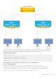
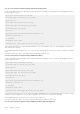
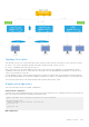
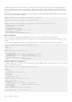
Table Of Contents
- Dell EMC SmartFabric OS10 User Guide Release 10.5.2
- Contents
- About this guide
- Change history
- Getting Started with Dell EMC SmartFabric OS10
- Switch with factory-installed OS10
- Baremetal switch with only ONIE installed
- Downgrade to Release 10.5.0.0 or earlier releases
- Downgrade to Release 10.5.1.0 or later releases
- Switch deployment options
- Remote access
- CLI Basics
- CONFIGURATION mode
- Check device status
- Command help
- Candidate configuration
- Copy running configuration
- Restore startup configuration
- Reload system image
- Filter show commands
- Common OS10 commands
- boot
- commit
- configure
- copy
- delete
- dir
- discard
- do
- end
- exit
- hostname
- license
- lock
- management route
- move
- no
- ping
- ping6
- reload
- show boot
- show candidate-configuration
- show environment
- show inventory
- show ip management-route
- show ipv6 management-route
- show license status
- show running-configuration
- show startup-configuration
- show system
- show version
- start
- system
- system-cli disable
- system-user linuxadmin disable
- system identifier
- terminal
- traceroute
- unlock
- username password role
- write
- Advanced CLI tasks
- Dell EMC SmartFabric OS10 zero-touch deployment
- Dell EMC SmartFabric OS10 provisioning
- SmartFabric Director
- System management
- System banners
- User session management
- Telnet server
- Simple Network Management Protocol
- System clock
- Network Time Protocol
- Precision Time Protocol
- Supported platforms
- Standards compliance
- PTP installation scale and limits
- Configuration notes
- Hybrid clocking
- Configure Precision Time Protocol
- View PTP information
- Example: Configure boundary clock with L2 transport method
- Example: Configure boundary clock with IPv4 multicast transport method
- Example: Configure boundary clock with IPv4 unicast transport method
- Example: Configure end-to-end transparent clock
- Example: Configure boundary clock with IPv4 unicast transport method and L3 VLAN
- Example: Configure PTP in a multinode setup
- PTP commands
- clear ptp counters
- debug ptp
- master
- ptp announce
- ptp clock
- ptp delay-mechanism
- ptp delay-req-min-interval
- ptp domain
- ptp enable
- ptp local-priority
- ptp priority1
- ptp priority2
- ptp role
- ptp source
- ptp sync-interval
- ptp system-time enable
- ptp transport
- ptp vlan
- show ptp
- show ptp clock
- show ptp counters
- show ptp foreign-masters
- show ptp interface
- show ptp parent
- show ptp peer
- show ptp servo
- show ptp time-properties
- slave
- source
- Synchronous Ethernet (SyncE)
- Supported platforms
- Standards compliance
- Clock source selection
- Manage clock selection
- Standby clock source states
- Restrictions and limitations
- Sample configurations
- SyncE commands
- clear sync-e counters
- clear sync-e lockout
- clear sync-e switch
- clear sync-e wait-restore-time
- debug sync-e
- show debug sync-e
- show sync-e
- show sync-e counters
- show sync-e esmc
- show sync-e interface
- sync-e enable
- sync-e esmc
- sync-e esmc-ext-ql-tlv disable
- sync-e hold-off-time
- sync-e lockout
- sync-e mode
- sync-e priority
- sync-e quality-level
- sync-e ssm-network-option
- sync-e switch force
- sync-e switch manual
- sync-e vlan
- sync-e wait-to-restore-time
- Dynamic Host Configuration Protocol
- Packet format and options
- DHCP server
- Automatic address allocation
- Hostname resolution
- Manual binding entries
- View DHCP Information
- DHCP relay agent
- Enable or disable DHCP Option-82
- DHCP relay agent options
- DHCPv4 relay counters
- DHCP relay without route leaking
- VRRP Virtual IP as Server Override (sub option 11)
- DHCP snooping
- System domain name and list
- DHCP commands
- DHCP relay commands
- clear ip dhcp-relay-counters
- ip helper-address
- ipv6 helper-address
- ip dhcp-relay information-option
- ip dhcp-relay vss
- ip dhcp-relay vss-info
- ip dhcp-relay link-selection
- ip dhcp-relay source-interface
- ip dhcp-relay server-override
- ip dhcp-relay source-interface
- ip dhcp-relay server-override
- ipv6 dhcp-relay interface-id
- ipv6 dhcp-relay prefix
- ipv6 dhcp-relay remote-id
- ipv6 dhcp-relay prefix remote-id
- ipv6 dhcp-relay hostname
- ipv6 dhcp-relay interface-id
- show ip dhcp-relay
- show ipv6 dhcp-relay
- show ip dhcp-relay-counters
- show vlt mismatch dhcp-relay
- show vlt mismatch dhcpv6-relay
- show vlt mismatch
- DHCP server commands
- DHCP snooping commands
- arp inspection
- arp inspection-trust
- arp inspection violation logging
- clear ip arp inspection statistics
- clear ip dhcp snooping binding
- ip dhcp snooping (global)
- ip dhcp snooping (interface)
- ip dhcp snooping binding
- ip dhcp snooping trust
- ip dhcp snooping verify mac-address
- show ip arp inspection database
- show ip arp inspection statistics
- show ip arp inspection logging
- show ip dhcp snooping binding
- DHCP relay commands
- DNS commands
- Containers
- Low Latency Modes
- Interfaces
- Ethernet interfaces
- Unified port groups
- Z9264F-ON port-group profiles
- Port-groups on S5200F-ON switches
- L2 mode configuration
- L3 mode configuration
- Fibre Channel interfaces
- Management interface
- VLAN interfaces
- User-configured default VLAN
- VLAN scale profile
- Loopback interfaces
- Port-channel interfaces
- Configure interface ranges
- Switch-port profiles
- Configure negotiation modes on interfaces
- Configure breakout mode
- Breakout auto-configuration
- Reset default configuration
- Forward error correction
- Energy-efficient Ethernet
- View interface configuration
- Viewing journal logs
- High-power optical modules
- Digital optical monitoring
- Default MTU Configuration
- Configure polling interval for Ethernet interface counters
- Interface commands
- channel-group
- default interface
- default vlan-id
- description (Interface)
- duplex
- enable dom
- enable dom traps
- feature auto-breakout
- fec
- interface breakout
- interface ethernet
- interface loopback
- interface mgmt
- interface null
- interface port-channel
- interface range
- interface vlan
- link-bundle-utilization
- link-bundle-monitor
- mode
- mode l3
- mtu
- negotiation
- port mode Eth
- port-group
- profile
- scale-profile vlan
- show interface
- show interface description
- show interface phy-eth
- show interface switchport
- show inventory media
- show inventory media details
- show link-bundle-utilization
- show port-channel summary
- show port-group
- show switch-port-profile
- show system
- show vlan
- shutdown
- speed (Fibre Channel)
- speed (Management)
- stats-monitor
- switch-port-profile
- switchport access vlan
- switchport mode
- switchport trunk allowed vlan
- wavelength
- default mtu
- show default mtu
- Fibre Channel
- Fibre Channel over Ethernet
- Terminology
- Virtual fabric
- Fibre Channel zoning
- F_Port on Ethernet
- Pinning FCoE traffic to a specific port of a port-channel
- Multiswitch fabric (E Port)
- Configure multiswitch fabric (E Port)
- Verify multiswitch fabric (E Port) configuration
- Multiswitch fabric (E Port) CLI commands
- show fc fspf interface
- clear fc fabric statistics
- clear fc flow-control-statistics
- clear fc fspf statistics
- clear fc ns switch statistics
- domain-id
- e_d_tov
- fc port-mode F | E
- feature fc
- fspf cost
- fspf dead-interval
- fspf hello-interval
- fspf hold-time
- fspf retransmit-interval
- principal-priority
- r_a_tov
- show fc fabric
- show fc fabric interface
- show fc fabric statistics
- show fc flow-control-statistics
- show fc fspf database
- show fc fspf neighbor
- show fc fspf route
- show fc ns fabric
- show fc ns fabric brief
- show fc ns switch statistics
- show fc switch
- show interface fibre channel
- show vfabric
- show vfabric fspf
- Multi-hop FIP-snooping bridge
- Configuration guidelines
- NPIV Proxy Gateway cascading
- Support for untagged VLAN in FCoE
- Single FCF per vFabric
- F_Port commands
- NPG commands
- F_Port and NPG commands
- FIP-snooping commands
- FCoE commands
- clear fcoe database
- clear fcoe statistics
- fcoe delay fcf-adv
- fcoe-pinned-port
- fcoe max-sessions-per-enodemac
- fcoe priority-bits
- lldp tlv-select dcbxp-appln fcoe
- re-balance fc npg sessions vfabric
- show fcoe enode
- show fcoe fcf
- show fcoe pinned-port
- show fcoe sessions
- show fcoe statistics
- show fcoe system
- show fcoe vlan
- show npg node-interface
- show npg uplink-interface
- Debug FC commands
- Layer 2
- 802.1X
- Far-end failure detection
- Link Aggregation Control Protocol
- Link Layer Discovery Protocol
- Mandatory TLVs
- Optional TLVs
- Configure LLDP
- Example: Advertise TLVs configuration
- View LLDP configuration
- View LLDP neighbor advertisements
- LLDP-MED
- LLDP commands
- clear lldp counters
- clear lldp table
- lldp enable
- lldp holdtime-multiplier
- lldp med fast-start-repeat-count
- lldp med
- lldp med network-policy
- lldp med network-policy (Interface)
- lldp med tlv-select
- lldp port-description-tlv advertise
- lldp receive
- lldp reinit
- lldp timer
- lldp tlv-select basic-tlv
- lldp management-addr-tlv virtual-ip
- lldp tlv-select dot1tlv
- lldp tlv-select dot3tlv
- lldp transmit
- lldp vlan-name-tlv allowed vlan
- show lldp interface
- show lldp errors
- show lldp med
- show lldp neighbors
- show lldp timers
- show lldp tlv-select interface
- show lldp traffic
- show network-policy profile
- Media Access Control
- Spanning-tree protocol
- Introduction to STP
- Supported STP modes
- Change STP modes
- Mode specific functionality
- Enable and disable STP
- Backward compatibility and interoperability
- BPDU extensions
- Recover from BPDU guard violations
- MAC flush optimization
- Spanning-tree link type for rapid state transitions
- Dynamic path cost calculation
- Debug facilities
- EdgePort
- Common STP commands
- clear spanning-tree counters
- debug spanning-tree
- errdisable detect cause bpduguard
- errdisable recovery cause bpduguard
- errdisable recovery interval
- clear spanning-tree detected-protocol
- spanning-tree bpdufilter
- spanning-tree bpduguard
- spanning-tree disable
- spanning-tree guard
- spanning-tree link-type
- spanning-tree mac-flush-timer
- spanning-tree mode rstp
- spanning-tree port
- show errdisable
- show spanning-tree interface
- Rapid per-VLAN spanning-tree
- RSTP/MSTP/Rapid-PVST Force Version
- Load balance and root selection
- Enable Rapid-PVST
- Select the root bridge
- Root assignment
- Global parameters
- Rapid-PVST commands
- show spanning-tree vlan
- spanning-tree vlan cost
- spanning-tree vlan disable
- spanning-tree vlan forward-time
- spanning-tree vlan force-version
- spanning-tree vlan hello-time
- spanning-tree vlan mac-flush-threshold
- spanning-tree vlan max-age
- spanning-tree vlan priority
- spanning-tree vlan priority (Interface)
- spanning-tree vlan root
- spanning-tree rapid-pvst default behavior
- show spanning-tree compatibility-mode
- spanning-tree rapid-pvst force-version
- Rapid Spanning-Tree Protocol
- Multiple Spanning-Tree
- Configure MSTP
- Create instances
- Root selection
- Non-Dell EMC hardware
- Region name or revision
- Modify parameters
- Interface parameters
- MST commands
- instance
- name
- revision
- spanning-tree mst
- spanning-tree msti
- spanning-tree mst configuration
- spanning-tree mst disable
- spanning-tree mst force-version
- spanning-tree mst forward-time
- spanning-tree mst hello-time
- spanning-tree mst mac-flush-threshold
- spanning-tree mst max-age
- spanning-tree mst max-hops
- show spanning-tree mst
- show spanning-tree msti
- Introduction to STP
- Virtual LANs
- Private VLANs
- PVLAN components
- Limitations
- Configuration notes
- Configure a PVLAN domain
- Extend PVLAN domain to another switch
- Configure PVLAN ports in a regular VLAN
- Configure an IPv4 address and local proxy ARP on a PVLAN interface
- Convert a secondary or promiscuous port to a regular L2 port
- Delete the primary and secondary VLANs
- View PVLAN information
- Interaction with other features
- PVLAN commands
- ip local-proxy-arp
- private-vlan mapping secondary-vlans
- private-vlan mode (VLAN mode)
- private-vlan mode (Port mode)
- show interface private-vlan
- show vlan private-vlan
- show vlan private-vlan primary
- show vlan private-vlan isolated
- show vlan private-vlan community
- show vlan private-vlan interface
- show vlan private-vlan mapping
- Example: PVLAN deployment with L2-L3 boundary at the spine layer
- Example: PVLAN deployment with L2-L3 boundary at the leaf layer
- Port monitoring
- Layer 3
- Virtual routing and forwarding
- Configure management VRF
- Configure non-default VRF instances
- VRF configuration
- View VRF instance information
- Static route leaking
- Route leaking
- Administrative distance for leaked routes
- VRF commands
- interface management
- ip domain-list vrf
- ip domain-name vrf
- ip vrf
- ip ftp vrf
- ip host vrf
- ip http vrf
- ip name-server vrf
- ip route-import
- ip route-export
- ipv6 route-import
- ipv6 route-export
- ip scp vrf
- ip sftp vrf
- ip tftp vrf
- ip vrf management
- match source-protocol
- redistribute imported-bgp-routes
- redistribute imported-ospf-routes
- redistribute l2vpn evpn
- set distance
- show hosts vrf
- show ip vrf
- update-source-ip
- Bidirectional Forwarding Detection
- BFD session states
- BFD three-way handshake
- BFD configuration
- Configure BFD globally
- BFD for BGP
- BFD for OSPF
- BFD for Static routes
- Enable BFD for all static routes
- Establishing BFD Sessions for IPv4 Static Routes
- Establishing BFD Sessions for IPv4 Static Routes in a non-default VRF instance
- Changing IPv4 static route session parameters
- Disabling BFD for IPv4 Static Routes
- Establishing BFD Sessions for IPv6 Static Routes
- Establishing BFD Sessions for IPv6 Static Routes in a non-default VRF instance
- Changing IPv6 static route session parameters
- Enable BFD for specific static routes
- Disabling BFD for IPv6 Static Routes
- BFD commands
- Border Gateway Protocol
- Sessions and peers
- Martian addresses
- Route reflectors
- Multiprotocol BGP
- Attributes
- Disable announcement of ASN values
- Selection criteria
- Weight and local preference
- Multiexit discriminators
- Origin
- AS path and next-hop
- Best path selection
- More path support
- Advertise cost
- 4-Byte AS numbers
- AS number migration
- Graceful restart
- Configure Border Gateway Protocol
- Enable BGP
- BGP over unnumbered interfaces
- Auto-unnumbered interfaces for BGP
- Configure Dual Stack
- Configure administrative distance
- Peer templates
- Neighbor fall-over
- Configure password
- Fast external fallover
- Passive peering
- Local AS
- AS number limit
- Redistribute routes
- Additional paths
- MED attributes
- Local preference attribute
- Weight attribute
- Enable multipath
- Route-map filters
- Route reflector clusters
- Aggregate routes
- Confederations
- Route dampening
- Timers
- Neighbor soft-reconfiguration
- Redistribute iBGP route to OSPF
- View BGP routes information
- Debug BGP
- Configuring BGP template
- Example - BGP in a VLT topology
- Example - Three-tier CLOS topology with eBGP
- BGP commands
- activate
- add-path
- add-path
- address-family
- advertisement-interval
- advertisement-start
- aggregate-address
- allowas-in
- always-compare-med
- as-notation
- bestpath as-path
- bestpath med
- bestpath router-id
- bgp dampening
- bgp redistribute-internal
- clear ip bgp
- clear ip bgp *
- clear ip bgp dampening
- clear ip bgp flap-statistics
- connection-retry-timer
- confederation
- client-to-client
- cluster-id
- debug ip bgp
- description
- default-metric
- default-originate
- distance bgp
- distribute-list
- bgp default local-preference
- ebgp-multihop
- enforce-first-as
- fall-over
- fast-external-fallover
- graceful-restart
- ibgp-ecmp-next-hop-self
- inherit
- inherit template
- ipv6 bgp unnumbered
- listen
- local-as
- log-neighbor-changes
- maximum-paths
- maximum-prefix
- neighbor
- network
- next-hop-self
- non-deterministic-med
- outbound-optimization
- password
- redistribute
- remote-as
- remove-private-as
- route-map
- route-reflector-client
- router bgp
- router-id
- send-community
- sender-side-loop-detection
- show ip bgp
- show ip bgp community
- show ip bgp community-list
- show ip bgp dampened-paths
- show ip bgp extcommunity-list
- show ip bgp filter-list
- show ip bgp flap-statistics
- show ip bgp ipv4 unicast
- show ip bgp ipv6 unicast
- show ip bgp neighbors
- show ip bgp peer-group
- show ip bgp summary
- show ip route
- show ipv6 route
- soft-reconfiguration inbound
- soft-reconfiguration inbound
- template
- timers
- update-source
- vrf
- weight
- Equal cost multi-path
- IPv4 routing
- IPv6 routing
- Enable or disable IPv6
- IPv6 addresses
- Stateless autoconfiguration
- Neighbor Discovery
- Duplicate address discovery
- Static IPv6 routing
- IPv6 destination unreachable
- IPv6 hop-by-hop options
- IPv6 Routing Header Type 0
- View IPv6 information
- IPv6 RA Guard
- Configure IPv6 RA guard
- IPv6 RA guard commands
- clear ipv6 nd ra-guard statistics
- device-role
- ipv6 nd ra-guard attach-policy
- ipv6 nd ra-guard enable
- ipv6 nd ra-guard logging enable
- ipv6 nd ra-guard policy
- mtu
- managed-config-flag
- match ra
- other-config-flag
- reachable-time
- retrans-timer
- router-lifetime
- router-preference maximum
- show config
- show ipv6 nd ra-guard policy
- show ipv6 nd ra-guard statistics
- show ipv6 nd ra-guard violation-details
- show vlt mismatch
- IPv6 commands
- clear ipv6 neighbors
- clear ipv6 route
- ipv6 address
- ipv6 address autoconfig
- ipv6 address dhcp
- ipv6 enable
- ipv6 address eui-64
- ipv6 address link-local
- ipv6 hop-by-hop
- ipv6 nd dad
- ipv6 nd hop-limit
- ipv6 nd managed-config-flag
- ipv6 nd max-ra-interval
- ipv6 nd mtu
- ipv6 nd other-config-flag
- ipv6 nd prefix
- ipv6 nd ra-lifetime
- ipv6 nd reachable-time
- ipv6 nd retrans-timer
- ipv6 nd send-ra
- ipv6 route
- ipv6 routing-header-type0 deny
- ipv6 unreachables
- show ipv6 neighbors
- show ipv6 route
- show ipv6 interface brief
- Open shortest path first
- Autonomous system areas
- Areas, networks, and neighbors
- Router types
- Designated and backup designated routers
- Link-state advertisements
- Router priority
- Shortest path first throttling
- Redistribute routes
- OSPFv2
- Enable OSPFv2
- Enable OSPFv2 in a non-default VRF instance
- Assign router identifier
- Stub areas
- Passive interfaces
- Fast convergence
- Interface parameters
- Default route
- Summary address
- Graceful restart
- OSPFv2 authentication
- Troubleshoot OSPFv2
- Debug OSPF
- OSPFv2 commands
- area default-cost
- area nssa
- area range
- area stub
- auto-cost reference-bandwidth
- clear ip ospf process
- clear ip ospf statistics
- debug ip ospfv2
- default-information originate
- default-metric
- fast-converge
- graceful-restart
- ip ospf area
- ip ospf authentication-key
- ip ospf cost
- ip ospf dead-interval
- ip ospf hello-interval
- ip ospf message-digest-key
- ip ospf mtu-ignore
- ip ospf network
- ip ospf passive
- ip ospf priority
- ip ospf retransmit-interval
- ip ospf transmit-delay
- log-adjacency-changes
- max-metric router-lsa
- maximum-paths
- redistribute
- router-id
- router ospf
- show ip ospf
- show ip ospf asbr
- show ip ospf database
- show ip ospf database asbr-summary
- show ip ospf database external
- show ip ospf database network
- show ip ospf database nssa external
- show ip ospf database opaque-area
- show ip ospf database opaque-as
- show ip ospf database opaque-link
- show ip ospf database router
- show ip ospf database summary
- show ip ospf interface
- show ip ospf routes
- show ip ospf statistics
- show ip ospf topology
- summary-address
- timers lsa arrival
- timers spf
- timers throttle lsa all
- OSPFv3
- Enable OSPFv3
- Enable OSPFv3 in a non-default VRF instance
- Assign Router ID
- Configure Stub Areas
- Enable Passive Interfaces
- Interface OSPFv3 Parameters
- Default route
- OSPFv3 IPsec authentication and encryption
- Troubleshoot OSPFv3
- OSPFv3 Commands
- area authentication
- area encryption
- area stub
- auto-cost reference-bandwidth
- clear ipv6 ospf process
- clear ipv6 ospf statistics
- debug ip ospfv3
- default-information originate
- ipv6 ospf area
- ipv6 ospf authentication
- ipv6 ospf cost
- ipv6 ospf dead-interval
- ipv6 ospf encryption
- ipv6 ospf hello-interval
- ipv6 ospf mtu-ignore
- ipv6 ospf network
- ipv6 ospf passive
- ipv6 ospf priority
- log-adjacency-changes
- maximum-paths
- redistribute
- router-id
- router ospfv3
- show ipv6 ospf
- show ipv6 ospf database
- show ipv6 ospf interface
- show ipv6 ospf neighbor
- show ipv6 ospf statistics
- timers spf (OSPFv3)
- Object tracking manager
- Policy-based routing
- Virtual Router Redundancy Protocol
- Virtual routing and forwarding
- Multicast
- Important notes
- Configure multicast routing
- Multicast Commands
- IPv4 multicast routing
- Internet Group Management Protocol
- Standards compliance
- Important notes
- Supported IGMP versions
- Query interval
- Last member query interval
- Maximum response time
- IGMP immediate leave
- Select an IGMP version
- IGMP commands
- clear ip igmp groups
- ip igmp immediate-leave
- ip igmp last-member-query-interval
- ip igmp query-interval
- ip igmp query-max-resp-time
- ip igmp snooping enable
- ip igmp snooping
- ip igmp snooping fast-leave
- ip igmp snooping last-member-query-interval
- ip igmp snooping mrouter
- ip igmp snooping querier
- ip igmp snooping query-interval
- ip igmp snooping query-max-resp-time
- ip igmp version
- show ip igmp groups
- show ip igmp interface
- show ip igmp snooping groups
- show ip igmp snooping groups detail
- show ip igmp snooping interface
- show ip igmp snooping mrouter
- show ip igmp snooping summary
- Protocol Independent Multicast
- PIM terminology
- Standards compliance
- PIM-SM
- PIM-SSM
- Configure expiry timers for S, G entries
- Configure static rendezvous point
- Configure dynamic RP using the BSR mechanism
- Configure designated router priority
- Update RP mapping cache with new RP configuration
- PIM join filters
- PIM neighbor filters
- PIM register filters
- PIM commands
- clear ip pim rp-mapping
- clear ip pim tib
- ip multicast-routing
- ip pim bsr-candidate
- ip pim bsr-candidate-timers
- ip pim bsr-timeout
- ip pim dr-priority
- ip pim join-filter
- ip pim neighbor-filter
- ip pim query-interval
- ip pim register-filter
- ip pim rp-address
- ip pim rp-candidate
- ip pim rp-candidate-timers
- ip pim sparse-mode
- ip pim sparse-mode sg-expiry-timer
- ip pim ssm-range
- show ip pim bsr-router
- show ip pim interface
- show ip pim mcache
- show ip pim neighbor
- show ip pim register-filter
- show ip pim rp
- show ip pim ssm-range
- show ip pim summary
- show ip pim tib
- show ip rpf
- Sample configuration: Multicast VRF using PIM-SM
- Anycast RP using PIM
- VLT multicast routing
- Internet Group Management Protocol
- IPv4 multicast traffic reduction
- IPv6 multicast traffic reduction
- Multicast Listener Discovery Protocol
- MLD snooping
- MLD snooping commands
- ipv6 mld snooping
- ipv6 mld snooping enable
- ipv6 mld snooping fast-leave
- ipv6 mld snooping last-member-query-interval
- ipv6 mld snooping mrouter
- ipv6 mld snooping querier
- ipv6 mld snooping query-interval
- ipv6 mld query-max-resp-time
- ipv6 mld version
- show ipv6 mld snooping groups
- show ipv6 mld snooping groups detail
- show ipv6 mld snooping interface
- show ipv6 mld snooping mrouter
- show ipv6 mld snooping summary
- Multicast Listener Discovery Protocol
- VXLAN
- VXLAN concepts
- VXLAN as NVO solution
- Configure VXLAN
- L3 VXLAN route scaling
- DHCP relay on VTEPs
- View VXLAN configuration
- VXLAN MAC addresses
- VXLAN commands
- hardware overlay-routing-profile
- interface virtual-network
- ip virtual-router address
- ip virtual-router mac-address
- member-interface
- nve
- remote-vtep
- show hardware overlay-routing-profile mode
- show interface virtual-network
- show nve remote-vtep
- show nve remote-vtep counters
- show nve vxlan-vni
- show virtual-network
- show virtual-network counters
- show virtual-network interface counters
- show virtual-network interface
- show virtual-network vlan
- show vlan (virtual network)
- source-interface loopback
- virtual-network
- virtual-network untagged-vlan
- vxlan-vni
- VXLAN MAC commands
- clear mac address-table dynamic nve remote-vtep
- clear mac address-table dynamic virtual-network
- show mac address-table count extended
- show mac address-table count nve
- show mac address-table count virtual-network
- show mac address-table extended
- show mac address-table nve
- show mac address-table virtual-network
- Example: VXLAN with static VTEP
- BGP EVPN for VXLAN
- BGP EVPN compared to static VXLAN
- VXLAN BGP EVPN operation
- Configure BGP EVPN for VXLAN
- VXLAN BGP EVPN routing
- BGP EVPN with VLT
- VXLAN BGP commands
- VXLAN EVPN commands
- Example: VXLAN with BGP EVPN with asymmetric IRB
- Example: VXLAN BGP EVPN — Multiple AS topology with asymmetric IRB
- Example: VXLAN BGP EVPN — Centralized L3 gateway with asymmetric IRB
- Example: VXLAN BGP EVPN — Border leaf gateway with asymmetric IRB
- Example: VXLAN BGP EVPN—Symmetric IRB
- Example - VXLAN BGP EVPN symmetric IRB with unnumbered BGP peering
- Example: Migrating from Asymmetric IRB to Symmetric IRB
- Example - Route leaking across VRFs in a VXLAN BGP EVPN symmetric IRB topology
- Controller-provisioned VXLAN
- UFT modes
- Security
- Switch security
- User management
- User accounts
- Privilege levels
- Passwords for user accounts
- User management commands
- disable
- enable
- enable password priv-lvl
- password-attributes
- password-attributes max-retry lockout-period console-exempt
- privilege
- service simple-password
- service obscure-password
- show users
- show privilege
- show running-configuration privilege
- system-user linuxadmin password
- system-user linuxadmin disable
- userrole inherit
- username password role
- AAA
- Boot security
- Bootloader protection
- Secure Boot
- Boot security commands
- boot protect disable username
- boot protect enable username password
- show boot protect
- show secure-boot pki-certificates
- show secure-boot
- secure-boot grub-key
- secure-boot verify
- secure-boot revoke key
- secure-boot protect startup-config
- secure-boot enable
- image verify
- image secure-install
- image gpg-key key-server
- Switch management access
- SSH server
- RESTCONF API
- Restrict SNMP access
- Limit concurrent login sessions
- Virtual terminal line ACLs
- Initiate an SSH session with another switch
- Switch management access
- ip ssh client cli enable
- ip ssh server enable
- ip ssh server challenge-response-authentication
- ip ssh server cipher
- ip ssh server hostbased-authentication
- ip ssh server kex
- ip ssh server mac
- ip ssh server password-authentication
- ip ssh server port
- ip ssh server pubkey-authentication
- ip ssh server vrf
- show ip ssh
- ssh
- show crypto ssh-key
- username sshkey
- username sshkey filename
- crypto ssh-key generate
- login concurrent-session limit
- line vty
- ipv6 access-class
- ip access-class
- Switch management statistics
- X.509v3 certificates
- X.509v3 concepts
- Public key infrastructure
- Manage CA certificates
- Certificate revocation
- Request and install host certificates
- Self-signed certificates
- Security profiles
- Cluster security
- SSH Smart Card Authentication
- Remote user authentication with a password
- Local user authentication with a password
- Local user authentication without a password
- General X.509v3 configuration for X.509v3 SSH authentication
- Configure remote user authentication with a password
- Configure local user authentication with a password
- Configure local user authentication without a password
- Security profile settings used by X.509v3 authentication
- Example: Configure RADIUS over TLS with X.509v3 certificates
- X.509v3 commands
- certificate
- cluster security-profile
- crypto ca-cert delete
- crypto ca-cert install
- crypto cdp add
- crypto cdp delete
- crypto cert delete
- crypto cert generate
- crypto cert install
- crypto crl delete
- crypto crl install
- crypto fips enable
- crypto security-profile
- peer-name-check
- revocation-check
- show crypto ca-certs
- show crypto cdp
- show crypto cert
- show crypto crl
- ip ssh server x509v3-authentication security-profile
- ocsp-check [ocsp-url]
- User management
- Network security
- Access control lists
- DHCP snooping
- 802.1X port access control
- Port security
- Related Videos
- Port security commands
- clear mac address-table secure
- errdisable recovery cause
- errdisable reset cause
- mac-learn
- mac-learn limit violation
- mac-move allow
- mac-move violation
- mac address-table static
- show switchport port-security
- switchport port-security (interface)
- switchport port-security (global)
- sticky
- aging
- show mac address-table secure
- show errdisable
- show mac address-table count
- Switch security
- OpenFlow
- OpenFlow logical switch instance
- OpenFlow controller
- OpenFlow version 1.3
- Ports
- Flow table
- Group table
- Meter table
- Instructions
- Action set
- Action types
- Counters
- OpenFlow protocol
- Connection setup TCP
- Supported controllers
- Flow table modification messages
- Message types
- Flow match fields
- Action structures
- Capabilities supported by the data path
- Multipart message types
- Switch description
- Property type
- Group configuration
- Controller roles
- Packet-in reasons
- Flow-removed reasons
- Error types from switch to controller
- OpenFlow use cases
- Configure OpenFlow
- OpenFlow commands
- OpenFlow-only mode commands
- Access Control Lists
- IP ACLs
- MAC ACLs
- Control-plane ACLs
- IP fragment handling
- L3 ACL rules
- Assign sequence number to filter
- Delete ACL rule
- L2 and L3 ACLs
- Assign and apply ACL filters
- Ingress ACL filters
- Egress ACL filters
- VTY ACLs
- SNMP ACLs
- Clear access-list counters
- IP prefix-lists
- Route-maps
- Match routes
- Set conditions
- Continue clause
- ACL flow-based monitoring
- Enable flow-based monitoring
- View ACL table utilization report
- ACL logging
- ACL commands
- clear ip access-list counters
- clear ipv6 access-list counters
- clear mac access-list counters
- deny
- deny (IPv6)
- deny (MAC)
- deny icmp
- deny icmp (IPv6)
- deny ip
- deny ipv6
- deny tcp
- deny tcp (IPv6)
- deny udp
- deny udp (IPv6)
- description
- ip access-group
- ip access-list
- ip as-path access-list
- ip community-list standard deny
- ip community–list standard permit
- ip extcommunity-list standard deny
- ip extcommunity-list standard permit
- ip prefix-list description
- ip prefix-list deny
- ip prefix-list permit
- ip prefix-list seq deny
- ip prefix-list seq permit
- ipv6 access-group
- ipv6 access-list
- ipv6 prefix-list deny
- ipv6 prefix-list description
- ipv6 prefix-list permit
- ipv6 prefix-list seq deny
- ipv6 prefix-list seq permit
- logging access-list mgmt burst
- logging access-list mgmt rate
- mac access-group
- mac access-list
- permit
- permit (IPv6)
- permit (MAC)
- permit icmp
- permit icmp (IPv6)
- permit ip
- permit ipv6
- permit tcp
- permit tcp (IPv6)
- permit udp
- permit udp (IPv6)
- remark
- seq deny
- seq deny (IPv6)
- seq deny (MAC)
- seq deny icmp
- seq deny icmp (IPv6)
- seq deny ip
- seq deny ipv6
- seq deny tcp
- seq deny tcp (IPv6)
- seq deny udp
- seq deny udp (IPv6)
- seq permit
- seq permit (IPv6)
- seq permit (MAC)
- seq permit icmp
- seq permit icmp (IPv6)
- seq permit ip
- seq permit ipv6
- seq permit tcp
- seq permit tcp (IPv6)
- seq permit udp
- seq permit udp (IPv6)
- show access-group
- show access-lists
- show acl-table-usage detail
- show control-plane logging
- show ip as-path-access-list
- show ip prefix-list
- show logging access-list
- Route-map commands
- continue
- match as-path
- match community
- match extcommunity
- match inactive-path-additive
- match interface
- match ip address
- match ip next-hop
- match ipv6 address
- match ipv6 next-hop
- match metric
- match origin
- match route-type
- match tag
- route-map
- set comm-list add
- set comm-list delete
- set community
- set extcomm-list add
- set extcomm-list delete
- set extcommunity
- set local-preference
- set metric
- set metric-type
- set next-hop
- set origin
- set tag
- set weight
- show route-map
- Quality of service
- Classification
- Marking Traffic
- Queuing
- Policing traffic
- Coloring traffic
- Modifying packet fields
- Shaping traffic
- Bandwidth allocation
- Strict priority queuing
- Rate adjustment
- Configure quality of service
- Example 1: Traffic classification and bandwidth allocation in VXLAN topology using CoS value
- Example 2: Traffic classification and bandwidth allocation in VXLAN topology using CoS value on access ports and DSCP value on network ports
- Buffer management
- Congestion avoidance
- Storm control
- RoCE for faster access and lossless connectivity
- Port to port-pipe and MMU mapping
- QoS VXLAN usecases
- QoS VXLAN examples
- QoS commands
- bandwidth
- buffer-statistics-tracking
- class
- class-map
- clear qos statistics
- clear qos statistics type
- control-plane
- control-plane-buffer-size
- flowcontrol
- hardware deep-buffer-mode
- match
- match cos
- match dscp
- match precedence
- match queue
- match vlan
- mtu
- pause
- pfc-cos
- pfc-max-buffer-size
- pfc-shared-buffer-size
- pfc-shared-headroom-buffer-size
- police
- policy-map
- priority
- priority-flow-control mode
- qos-group dot1p
- qos-group dscp
- qos-map traffic-class
- qos-rate-adjust
- queue-limit
- queue bandwidth
- queue qos-group
- queue qos-group (Z9332F-ON)
- random-detect (interface)
- random-detect (queue)
- random-detect color
- random-detect ecn
- random-detect ecn
- random-detect pool
- random-detect weight
- service-policy
- set cos
- set dscp
- set qos-group
- shape
- show class-map
- show control-plane buffers
- show control-plane buffer-stats
- show control-plane info
- show control-plane statistics
- show hardware deep-buffer-mode
- show interface priority-flow-control
- show qos interface
- show policy-map
- show qos control-plane
- show qos egress buffers interface
- show qos egress buffer-statistics-tracking
- show qos egress buffer-stats interface
- show qos headroom-pool buffer-statistics-tracking
- show qos ingress buffers interface
- show qos ingress buffer-statistics-tracking
- show qos ingress buffer-stats interface
- show qos maps
- show qos maps (Z9332F-ON)
- show qos port-map details
- show qos-rate-adjust
- show qos service-pool buffer-statistics-tracking
- show qos system
- show qos system buffers
- show qos wred-profile
- show queuing statistics
- system qos
- trust dot1p-map
- trust dscp-map
- trust-map
- wred
- Virtual Link Trunking
- Terminology
- VLT domain
- VLT interconnect
- Graceful LACP with VLT
- Configure VLT
- Configure VRRP Active-Active mode
- Migrate VMs across data centers with eVLT
- View VLT information
- Delay-restore for orphan ports
- Example: Configure RSPAN in VLT network
- VLT commands
- backup destination
- delay-restore
- delay-restore-port enable
- delay-restore-port timeout
- discovery-interface
- peer-routing
- peer-routing-timeout
- primary-priority
- show running-configuration vlt
- show spanning-tree virtual-interface
- show delay-restore-port
- show vlt
- show vlt domain-id delay restore orphan port
- show vlt backup-link
- show vlt egress-mask-rule
- show vlt error-disabled-ports
- show vlt mac-inconsistency
- show vlt mismatch
- show vlt role
- show vlt vlt-port-detail
- vlt-domain
- vlt delay-restore orphan-port enable
- vlt delay-restore orphan-port ignore vlti-failure
- vlt-port-channel
- vlt-mac
- vrrp mode active-active
- Uplink Failure Detection
- Converged data center services
- sFlow
- Telemetry
- RESTCONF API
- Troubleshoot Dell EMC SmartFabric OS10
- Diagnostic tools
- Recover Linux password
- Recover OS10 user name password
- Restore factory defaults
- SupportAssist
- Important notes
- Configure SupportAssist
- Set company name
- Set contact information
- Schedule activity
- View status
- View warranty information
- View SupportAssist logs
- List of country names and codes
- SupportAssist commands
- Support bundle
- System monitoring
- Monitor CPU Utilization
- Monitor Memory Utilization
- Log into OS10 device
- Frequently asked questions
- Support resources

The topology consists of two VTEPs with VTEP IPs 100.1.1.1 and 200.1.1.1 respectively. The VTEPs are connected with the
Spine node via L3 direct uplinks. Each VTEP has two hosts connected to the access ports, which are part of VLAN 10 and 20
respectively. These two access ports are configured to be part of virtual-network 100 in the VTEP.
Virtual Network Configuration:
virtual-network 100
!
member-interface ethernet1/1/1 vlan-tag 10
member-interface ethernet1/1/2 vlan-tag 20
!
vxlan-vni 100
QoS in VxLAN Access Ports (Traffic from Access ports to Access and Network ports)
Use Case 1: Default Behavior
Consider the incoming traffic in port 1/1/1 of VTEP-1 consists of dot1p priority of 3 and DSCP value of 3.
The below behavior will be seen in the encapsulated traffic flowing out of Port 1/1/3 and the other access port 1/1/2.
The Encapsulated traffic flowing out of port 1/1/3 will have DSCP value of 3 and do not have the dot1p priority value.
The Traffic egress out of port 1/1/2 will have VLAN 20, dot1p priority 3 and DSCP value of 3.
Quality of service
1563