
Deployment Guide
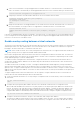
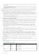

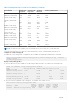
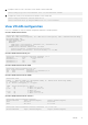
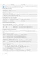
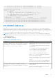
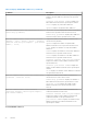
Table Of Contents
- VXLAN and BGP EVPN Configuration Guide for Dell EMC SmartFabric OS10 Release 10.5.0
- VXLAN
- VXLAN concepts
- VXLAN as NVO solution
- Configure VXLAN
- L3 VXLAN route scaling
- Overlay ECMP for L3 prefix routes
- DHCP relay on VTEPs
- View VXLAN configuration
- VXLAN MAC addresses
- VXLAN commands
- hardware overlay-ecmp-profile mode
- hardware overlay-routing-profile
- interface virtual-network
- ip virtual-router address
- ip virtual-router mac-address
- member-interface
- nve
- remote-vtep
- show hardware overlay-ecmp-profile mode
- show hardware overlay-routing-profile mode
- show interface virtual-network
- show nve remote-vtep
- show nve remote-vtep counters
- show nve vxlan-vni
- show virtual-network
- show virtual-network counters
- show virtual-network interface counters
- show virtual-network interface
- show virtual-network vlan
- show vlan (virtual network)
- source-interface loopback
- virtual-network
- virtual-network untagged-vlan
- vxlan-vni
- VXLAN MAC commands
- clear mac address-table dynamic nve remote-vtep
- clear mac address-table dynamic virtual-network
- show mac address-table count extended
- show mac address-table count nve
- show mac address-table count virtual-network
- show mac address-table extended
- show mac address-table nve
- show mac address-table virtual-network
- Example: VXLAN with static VTEP
- BGP EVPN for VXLAN
- BGP EVPN compared to static VXLAN
- VXLAN BGP EVPN operation
- Disable RT ASN in BGP EVPN
- Configure BGP EVPN for VXLAN
- VXLAN BGP EVPN routing
- BGP EVPN with VLT
- VXLAN BGP commands
- VXLAN EVPN commands
- Example: VXLAN with BGP EVPN
- Example: VXLAN BGP EVPN — Multiple AS topology
- Example: VXLAN BGP EVPN — Centralized L3 gateway
- Example: VXLAN BGP EVPN — Border leaf gateway with asymmetric IRB
- Example: VXLAN BGP EVPN—Symmetric IRB
- Controller-provisioned VXLAN
- Support resources

Table 1. MAC address for all VTEPs (continued)
Virtual network VTEP Anycast gateway MAC address
VTEP 3
00.11.22.33.44.55
VNID 13 VTEP 1
VTEP 2
VTEP 3
00.11.22.33.44.55
00.11.22.33.44.55
00.11.22.33.44.55
● Configure a unique IP address on the virtual-network interface on each VTEP across all virtual networks. Configure the same
anycast gateway IP address on all VTEPs in a virtual-network subnet. For example:
Table 2. IP address on the virtual-network interface on each VTEP
Virtual network VTEP Virtual-network IP
address
Anycast gateway IP address
VNID 11 VTEP 1
VTEP 2
VTEP 3
10.10.1.201
10.10.1.202
10.10.1.203
10.10.1.254
10.10.1.254
10.10.1.254
VNID 12 VTEP 1
VTEP 2
VTEP 3
10.20.1.201
10.20.1.202
10.20.1.203
10.20.1.254
10.20.1.254
10.20.1.254
VNID 13 VTEP 1
VTEP 2
VTEP 3
10.30.1.201
10.30.1.202
10.30.1.203
10.30.1.254
10.30.1.254
10.30.1.254
Advertise VXLAN source IP address
1. Advertise the IP address of the local source tunnel interface to all VTEPs in the underlay IP network using the existing
routing infrastructure. This example uses OSPF to advertise the VXLAN source IP address on Ethernet1/1/3, which is the
underlay network-facing interface:
OS10(config)# router ospf 100
OS10(config-ospf)# router-id 110.111.170.195
OS10(config-ospf)# exit
OS10(config)# interface ethernet1/1/3
OS10(config-if-eth1/1/3)# ip ospf 100 area 0.0.0.0
OS10(config-if-eth1/1/3)# exit
OS10(config)# interface loopback 1
OS10(config-if-lo-1)# ip ospf 100 area 0.0.0.0
Each VTEP switch in the underlay IP network learns the IP address of the VXLAN source interface. If a remote VTEP switch
is not reachable, its status displays as DOWN in the show nve remote-vtep output.
2. Configure the MTU value on L3 underlay network-facing interfaces in Interface mode to be at least 50 bytes higher than the
MTU on the server-facing links to allow for VXLAN encapsulation. The range is from 1312 to 9216.
mtu value
3. Return to CONFIGURATION mode.
exit
VXLAN
13