
Installation and Service Manual


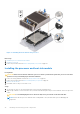


Table Of Contents
- Dell EMC PowerEdge R650xs Installation and Service Manual
- Contents
- About this document
- Dell EMC PowerEdge R650xs system overview
- Initial system setup and configuration
- Minimum to POST and system management configuration validation
- Installing and removing system components
- Safety instructions
- Before working inside your system
- After working inside your system
- Recommended tools
- Optional front bezel
- System cover
- Drive backplane cover
- Air shroud
- Cooling fans
- Intrusion switch module
- Drives
- Optional optical drive
- Drive backplane
- Cable routing
- System memory
- Processor and heat sink module
- Expansion cards and expansion card risers
- Drive cage
- Optional serial COM port
- MicroSD card
- Optional BOSS S1 card
- Optional IDSDM module
- Optional OCP card
- Front mounting front PERC module
- System battery
- Optional internal USB card
- VGA module
- Power supply unit
- Power interposer board
- System board
- Trusted Platform Module
- Control panel
- Jumpers and connectors
- System diagnostics and indicator codes
- Getting help
- Documentation resources

3. To verify if the memory module has been installed properly, press F2 and navigate to System Setup Main Menu > System
BIOS > Memory Settings. In the Memory Settings screen, the System Memory Size must reflect the updated capacity of
the installed memory.
4. If the System Memory Size is incorrect, one or more of the memory modules may not be installed properly. Ensure that the
memory modules are firmly seated in their sockets.
5. Run the system memory test in system diagnostics.
Processor and heat sink module
This is a service technician replaceable part only.
Removing a processor and heat sink module
Prerequisites
1. Follow the safety guidelines listed in the Safety instructions on page 25.
2. Follow the procedure listed in the Before working inside your system on page 26.
3. Remove the air shroud.
NOTE: The heat sink and processor are hot to touch for some time after the system has been powered down. Allow the
heat sink and processor to cool down before handling them.
Steps
1. Ensure all four anti-tilt wires are in the locked position (outward position), and then using a Torx T30 tool, loosen the captive
nuts on the heat sink in the order that is mentioned below:
a. Loosen the first nut three turns.
b. Loosen the nut diagonally opposite to the nut you loosened first.
c. Repeat the procedure for the remaining two nuts.
d. Return to the first nut to loosen it completely.
2. Set the Anti-Tilt wires to the unlocked position (inward position).
Figure 52. Loosening the nuts and set the Anti-Tilt wires to the unlocked position
3. Lift the processor and heat sink module (PHM) from the system and set the PHM aside with the processor side facing up.
62
Installing and removing system components