
Installation and Service Manual

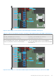


Table Of Contents
- Dell EMC PowerEdge R650xs Installation and Service Manual
- Contents
- About this document
- Dell EMC PowerEdge R650xs system overview
- Initial system setup and configuration
- Minimum to POST and system management configuration validation
- Installing and removing system components
- Safety instructions
- Before working inside your system
- After working inside your system
- Recommended tools
- Optional front bezel
- System cover
- Drive backplane cover
- Air shroud
- Cooling fans
- Intrusion switch module
- Drives
- Optional optical drive
- Drive backplane
- Cable routing
- System memory
- Processor and heat sink module
- Expansion cards and expansion card risers
- Drive cage
- Optional serial COM port
- MicroSD card
- Optional BOSS S1 card
- Optional IDSDM module
- Optional OCP card
- Front mounting front PERC module
- System battery
- Optional internal USB card
- VGA module
- Power supply unit
- Power interposer board
- System board
- Trusted Platform Module
- Control panel
- Jumpers and connectors
- System diagnostics and indicator codes
- Getting help
- Documentation resources

Removing a memory module
Prerequisites
1. Follow the safety guidelines listed in the Safety instructions on page 25.
2. Follow the procedure listed in the Before working inside your system on page 26.
3. Remove the air shroud.
WARNING: The memory modules are hot to touch for some time after the system has been powered off. Allow
the memory modules to cool before handling them.
NOTE: To ensure proper system cooling, memory module blanks must be installed in any memory socket that is not
occupied. Remove memory module blanks only if you intend to install memory modules in those sockets.
Steps
1. Locate the appropriate memory module socket.
2. To release the memory module from the socket, simultaneously press the ejectors on both ends of the memory module
socket to fully open.
CAUTION: Handle each memory module only by the card edges, ensuring not to touch the middle of the
memory module or metallic contacts.
3. Lift the memory module away from the system.
Figure 50. Removing a memory module
Next steps
1. Replace the memory module.
2. If you are removing the memory module permanently, install a memory module blank. The procedure to install a memory
module blank is similar to that of the memory module.
NOTE:
When operating your system with single processor, install memory module blanks in processor 2 memory
sockets.
.
60
Installing and removing system components