
Installation and Service Manual

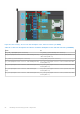
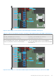


Table Of Contents
- Dell EMC PowerEdge R650xs Installation and Service Manual
- Contents
- About this document
- Dell EMC PowerEdge R650xs system overview
- Initial system setup and configuration
- Minimum to POST and system management configuration validation
- Installing and removing system components
- Safety instructions
- Before working inside your system
- After working inside your system
- Recommended tools
- Optional front bezel
- System cover
- Drive backplane cover
- Air shroud
- Cooling fans
- Intrusion switch module
- Drives
- Optional optical drive
- Drive backplane
- Cable routing
- System memory
- Processor and heat sink module
- Expansion cards and expansion card risers
- Drive cage
- Optional serial COM port
- MicroSD card
- Optional BOSS S1 card
- Optional IDSDM module
- Optional OCP card
- Front mounting front PERC module
- System battery
- Optional internal USB card
- VGA module
- Power supply unit
- Power interposer board
- System board
- Trusted Platform Module
- Control panel
- Jumpers and connectors
- System diagnostics and indicator codes
- Getting help
- Documentation resources

Table 26. Connector descriptions for No drive configuration
From To
SYS_PWR2 (system board power connector) CPU_PWR2 (PSU power connector)
System memory
System memory guidelines
The PowerEdge R650xs system supports DDR4 registered DIMMs (RDIMMs). System memory holds the instructions that are
executed by the processor.
Your system contains 16 memory sockets organized into 8 channels per processor.
Memory channels are organized as follows:
Table 27. Memory channels
Processor Channel A Channel B Channel C Channel D Channel E Channel F Channel G Channel H
Processor 1 A1 A5 A3 A7 A2 A6 A4 A8
Processor 2 B1 B5 B3 B7 B2 B6 B4 B8
Figure 49. Memory socket location
58
Installing and removing system components