
Installation and Service Manual


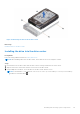


Table Of Contents
- Dell EMC PowerEdge R650xs Installation and Service Manual
- Contents
- About this document
- Dell EMC PowerEdge R650xs system overview
- Initial system setup and configuration
- Minimum to POST and system management configuration validation
- Installing and removing system components
- Safety instructions
- Before working inside your system
- After working inside your system
- Recommended tools
- Optional front bezel
- System cover
- Drive backplane cover
- Air shroud
- Cooling fans
- Intrusion switch module
- Drives
- Optional optical drive
- Drive backplane
- Cable routing
- System memory
- Processor and heat sink module
- Expansion cards and expansion card risers
- Drive cage
- Optional serial COM port
- MicroSD card
- Optional BOSS S1 card
- Optional IDSDM module
- Optional OCP card
- Front mounting front PERC module
- System battery
- Optional internal USB card
- VGA module
- Power supply unit
- Power interposer board
- System board
- Trusted Platform Module
- Control panel
- Jumpers and connectors
- System diagnostics and indicator codes
- Getting help
- Documentation resources

Figure 33. 8 x 2.5-inch drive backplane
1. BP_PWR_1 (backplane power and signal cable to PIB)
Figure 34. 10 x 2.5-inch NVMe drive backplane
1. DST_PA3 (PCIe/NVMe connector) 2. DST_SA2 (backplane to front PERC)
3. DST_PB2 (PCIe/NVMe connector) 4. DST_PA2 (PCIe/NVMe connector)
5. DST_SA1 (PERC to backplane) 6. BP_PWR_1 (backplane power and signal cable to PIB)
7. DST_PA1 (PCIe/NVMe connector) 8. DST_PB1 (PCIe/NVMe connector)
Removing the backplane
Prerequisites
CAUTION:
To prevent damage to the drives and backplane, remove the drives from the system before removing
the backplane.
CAUTION: Note the number of each drive and temporarily label them before you remove the drive so that you
can reinstall them in the same location.
NOTE: The procedure to remove the backplane is similar for all backplane configurations.
1. Follow the safety guidelines listed in the Safety instructions on page 25.
2. Follow the procedure listed in the Before working inside your system on page 26.
3. Remove the air shroud.
4. Remove the backplane cover
5. Remove all the drives.
6. Disconnect the VGA cable from the system board.
NOTE: Observe the routing of the cable as you remove it from the system.
7. If installed, disconnect the optical drive signal and power cables from the system.
8. Disconnect the drive backplane cables from the connectors on the system board.
Steps
1. Press the blue release tabs to disengage the drive backplane from the hooks on the system.
2. Lift the drive backplane out of the system.
NOTE:
To avoid damaging the backplane, ensure that you move the control panel cables from the cable routing clips
before removing the backplane.
Installing and removing system components 47