
Installation and Service Manual


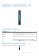
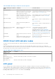


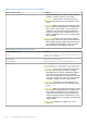
Table Of Contents
- Dell EMC PowerEdge R650xs Installation and Service Manual
- Contents
- About this document
- Dell EMC PowerEdge R650xs system overview
- Initial system setup and configuration
- Minimum to POST and system management configuration validation
- Installing and removing system components
- Safety instructions
- Before working inside your system
- After working inside your system
- Recommended tools
- Optional front bezel
- System cover
- Drive backplane cover
- Air shroud
- Cooling fans
- Intrusion switch module
- Drives
- Optional optical drive
- Drive backplane
- Cable routing
- System memory
- Processor and heat sink module
- Expansion cards and expansion card risers
- Drive cage
- Optional serial COM port
- MicroSD card
- Optional BOSS S1 card
- Optional IDSDM module
- Optional OCP card
- Front mounting front PERC module
- System battery
- Optional internal USB card
- VGA module
- Power supply unit
- Power interposer board
- System board
- Trusted Platform Module
- Control panel
- Jumpers and connectors
- System diagnostics and indicator codes
- Getting help
- Documentation resources

Table 45. NIC indicator codes (continued)
NIC indicator codes Condition
Link indicator is green, and activity indicator is blinking
green.
Indicates that the NIC is connected to a valid network at its maximum
port speed, and data is being sent or received.
Link indicator is amber, and activity indicator is blinking
green.
Indicates that the NIC is connected to a valid network at less than its
maximum port speed, and data is being sent or received.
Link indicator is green, and activity indicator is off. Indicates that the NIC is connected to a valid network at its maximum
port speed, and data is not being sent or received.
Link indicator is amber, and activity indicator is off. Indicates that the NIC is connected to a valid network at less than its
maximum port speed, and data is not being sent or received.
Link indicator is blinking green, and activity is off. Indicates that the NIC identity is enabled through the NIC
configuration utility.
Power supply unit indicator codes
AC and DC power supply units (PSUs) have an illuminated translucent handle that serves as an indicator. The indicator shows if
power is present or if a power fault has occurred.
Figure 137. AC PSU status indicator
1. AC PSU handle
2. Socket
3. Release latch
Table 46. AC PSU status indicator codes
Power indicator codes Condition
Green Indicates that a valid power source is connected to the PSU
and the PSU is operational.
Blinking amber Indicates an issue with the PSU.
Not powered on Indicates that the power is not connected to the PSU.
Blinking green Indicates that the firmware of the PSU is being updated.
CAUTION: Do not disconnect the power cord or
unplug the PSU when updating firmware. If firmware
update is interrupted, the PSUs will not function.
Blinking green and powers off When hot-plugging a PSU, it blinks green five times at a rate
of 4 Hz and powers off. This indicates a PSU mismatch due to
efficiency, feature set, health status, or supported voltage.
CAUTION: If two PSUs are installed, both the PSUs
must have the same type of label; for example,
Extended Power Performance (EPP) label. Mixing
PSUs from previous generations of PowerEdge
servers is not supported, even if the PSUs have the
System diagnostics and indicator codes 139