
Installation and Service Manual


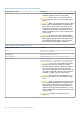
Table Of Contents
- Dell EMC PowerEdge R650xs Installation and Service Manual
- Contents
- About this document
- Dell EMC PowerEdge R650xs system overview
- Initial system setup and configuration
- Minimum to POST and system management configuration validation
- Installing and removing system components
- Safety instructions
- Before working inside your system
- After working inside your system
- Recommended tools
- Optional front bezel
- System cover
- Drive backplane cover
- Air shroud
- Cooling fans
- Intrusion switch module
- Drives
- Optional optical drive
- Drive backplane
- Cable routing
- System memory
- Processor and heat sink module
- Expansion cards and expansion card risers
- Drive cage
- Optional serial COM port
- MicroSD card
- Optional BOSS S1 card
- Optional IDSDM module
- Optional OCP card
- Front mounting front PERC module
- System battery
- Optional internal USB card
- VGA module
- Power supply unit
- Power interposer board
- System board
- Trusted Platform Module
- Control panel
- Jumpers and connectors
- System diagnostics and indicator codes
- Getting help
- Documentation resources

3. OCP NIC 3.0 Connector 4. DIMMs for processor 2 Channels E, F, G, H
5. TPM Connector 6. PCIe Connector 7 (SL7_CPU1_PA4)
7. Serial Port Connector 8. BOSS Riser Slot (PCH)
9. PCIe Connector 8 (SL8_CPU1_PB4) 10. PCH
11. Front VGA 12. PWRD_EN (Jumpers)
13. NVRAM_CLR(Jumpers) 14. Riser 1 Connector (Processor 1)
15. SATA Connector S9 (SL9_PCH_SA1) 16. DIMMs for processor 1 Channels A, B, C, D
17. Right Control Panel 18. Processor 1
19. PCIe Connector 4 (SL4_CPU1_PA2) 20. DIMMs for processor 1 Channels E, F, G, H
21. PCIe Connector 3 (SL3_CPU1_PB2) 22. System Power Connector 2
23. Processor 2 24. PCIe Connector 2 (SL2_CPU2_PA1)
25. PCIe Connector 1(SL1_CPU2_PB1) 26. Fan Signal 1
27. Fan Signal 2 28. Left Control Panel
29. PIB Signal 1 30. PIB Signal 2
31. Intrusion Switch Connector 32. System Power Connector 1
33. DIMMs for processor 2 Channels E, F, G, H 34. Backplane Signal and Power 0
35. Coin cell battery
System board jumper settings
For information about resetting the password jumper to disable a password, see the Disabling a forgotten password section.
Table 37. System board jumper settings
Jumper Setting Description
PWRD_EN The BIOS password feature is enabled.
The BIOS password feature is disabled. The BIOS password is
now disabled and you are not allowed to set a new password.
NVRAM_CLR The BIOS configuration settings are retained at system boot.
The BIOS configuration settings are cleared at system boot.
CAUTION: Be careful when changing the BIOS settings. The BIOS interface is designed for advanced users. Any
change in the setting could prevent your system from starting correctly and you might have potential loss of
data.
Disabling a forgotten password
The software security features of the system include a system password and a setup password. The password jumper enables or
disables password features and clears any password(s) currently in use.
Prerequisites
CAUTION:
Many repairs may only be done by a certified service technician. You should only perform
troubleshooting and simple repairs as authorized in your product documentation, or as directed by the online or
telephone service and support team. Damage due to servicing that is not authorized by Dell is not covered by
your warranty. Read and follow the safety instructions that are shipped with your product.
Steps
1. Power off the system and all attached peripherals. Disconnect the system from the electrical outlet, and disconnect the
peripherals.
Jumpers and connectors
131