
Installation and Service Manual
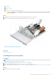


Table Of Contents
- Dell EMC PowerEdge R650xs Installation and Service Manual
- Contents
- About this document
- Dell EMC PowerEdge R650xs system overview
- Initial system setup and configuration
- Minimum to POST and system management configuration validation
- Installing and removing system components
- Safety instructions
- Before working inside your system
- After working inside your system
- Recommended tools
- Optional front bezel
- System cover
- Drive backplane cover
- Air shroud
- Cooling fans
- Intrusion switch module
- Drives
- Optional optical drive
- Drive backplane
- Cable routing
- System memory
- Processor and heat sink module
- Expansion cards and expansion card risers
- Drive cage
- Optional serial COM port
- MicroSD card
- Optional BOSS S1 card
- Optional IDSDM module
- Optional OCP card
- Front mounting front PERC module
- System battery
- Optional internal USB card
- VGA module
- Power supply unit
- Power interposer board
- System board
- Trusted Platform Module
- Control panel
- Jumpers and connectors
- System diagnostics and indicator codes
- Getting help
- Documentation resources

CAUTION: Do not lift the system board by holding a memory module, processor, or other components.
CAUTION: Take care not to damage the system identification button while placing the system board into the
chassis.
2. Using the system board holder, lower the system board it into the system.
3. Incline the system board at an angle and align the connectors on the system board with the slots on the rear of the chassis
until the connectors are firmly seated in the slots.
Figure 126. Installing the system board
Next steps
1. Replace the following components:
a. Trusted Platform Module (TPM)
NOTE: The TPM Module must be replaced only while installing new system board.
b. Expansion cards
c. Expansion card risers
d. M.2 BOSS riser
e. Processor
f. Heat sink
g. Memory modules
h. OCP card
i. Air shroud
2. Reconnect all cables to the system board.
NOTE:
Ensure that the cables inside the system are routed along the chassis wall and secured using the cable securing
bracket.
3. Ensure that you perform the following steps:
a. Use the Easy Restore feature to restore the Service Tag. See the Restoring the system by using the Easy Restore
feature section.
b. If the service tag is not backed up in the backup flash device, enter the system service tag manually. See the Manually
update the Service Tag by using System Setup section.
c. Update the BIOS and iDRAC versions.
122
Installing and removing system components