
Deployment Guide


17 S
caleIO/VxFlex OS IP Fabric Best Practice and Deployment Guide with OS10EE | version 1.0
Interface and IP configuration
Link
Source
switch
Source
interface
Source
IP
Network
Destination
switch
Destination
interface
Destination
IP
A
Leaf 1A
eth1/1/45
.1
192.168.1.0/31
Spine 1
eth1/1/1
.0
B
Leaf 1A
eth1/1/46
.1
192.168.2.0/31
Spine 2
eth1/1/1
.0
C
Leaf 1B
eth1/1/45
.3
192.168.1.2/31
Spine 1
eth1/1/2
.2
D
Leaf 1B
eth1/1/46
.3
192.168.2.2/31
Spine 2
eth1/1/2
.2
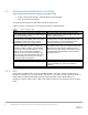
Figure 7 shows the links from Table 3
Point-to-point interface IP addressing
Note: The example point-to-point addresses use a 31-bit mask to prevent unnecessary sprawling of internal
addresses. This IP scheme is optional and covered in RFC 3021.
3.2.5 Interface/IP configuration
Table 4 outlines the subnets, VLANs and default gateways for the broadcast networks. Notice that the same
VLAN IDs, with different networks, repeat in each rack. The VLANs and subnets are configured on both leaf
switches and advertised through the routing instance at the same cost. ECMP spreads server traffic flow
across all uplinks.
VLAN and subnet examples
Rack
ID
Network Name
Subnet
VLAN
Gateway
1
ESXi management
172.17.31.0/24
1731
172.17.31.253
1
vmotion
172.17.32.0/24
1732
172.17.32.253
1
ScaleIO-
management
172.17.33.0/24
1733
172.17.33.253
1
ScaleIO-data01
172.17.34.0/24
1734
172.17.34.253