
Deployment Guide
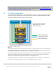
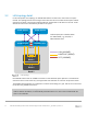

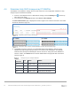

Table Of Contents
- 1 Introduction
- 2 Hardware overview
- 3 Topology overview
- 4 Preparation
- 5 S4148U-ON switch configuration
- 6 S4148U-ON validation
- 7 Configure Unity FC storage
- 8 Configure storage on ESXi hosts
- 9 Configure ESXi hosts for LAN traffic
- A Validated components
- B Technical support and resources
- C Support and feedback

11 Dell EMC Networking FCoE-to-Fibre Channel Deployment with S4148U-ON in F_port Mode | version 1.0
Note: Using a leaf-spine network in the data center is considered a best practice. For detailed leaf-spine
network configuration instructions, including spine switch configuration, refer to Dell EMC Networking Layer
3 Leaf-Spine Deployment and Best Practices with OS10.
3.1 FC SAN topology detail
For the SAN portion of the topology, each S4148U-ON switch is placed in F_port mode. This enables direct
connections to N_port devices such as FC storage without the need for an additional dedicated FC switch.
The FC SAN topology used in this guide is shown in Figure 8.
Rack 1
S4148U-Leaf1 S4148U-Leaf2
Unity 500F
1
R640-1
SP B
SP A
0
0
1
1
FC SAN A (16Gb FC)
FC SAN B (16Gb FC)
FCoE/LAN (10GbE)
eth31eth32fc1 fc3
eth31 eth32 fc1fc3
Leaf port numbers shown are
abbreviated, e.g., fc1/1/1 is
abbreviated as fc1.
2
R640-2
1
2
FC SAN topology
Each PowerEdge R640 server in this deployment contains one QLogic 57800 rack server network daughter
card (rNDC) with two 10GbE CNA ports. These connections carry converged LAN and SAN (FCoE) traffic.
Each CNA port is connected to an Ethernet port on an S4148U-ON as shown.
For SAN traffic, S4148U-ON switches serve as Fibre Channel Forwarders (FCFs). They decapsulate the FC
payload from incoming FCoE frames and forward them to the storage array. Incoming FC frames from
storage are encapsulated using FCoE and forwarded to the appropriate CNA.
The Unity 500F storage array contains redundant storage processors, SP A and SP B. FC ports from the
Unity SPs are directly connected to FC ports on the S4148U-ON switches as shown.