
Install Guide
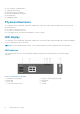
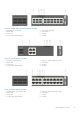
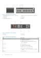
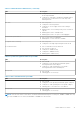
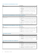
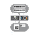

Table 5. S4100–ON Series LED behavior (continued)
LED Description
● Solid green—Normal operation; fan powered and running
at the expected RPM
● Solid yellow—Fan failed—including incompatible airflow
direction when you insert the PSU or fan trays with
differing airflows
PSU LED
● Off—No power
● Solid green—Normal operation
● Solid yellow—Power supply critical event causing a
shutdown.
● Blinking yellow—PSU warning event; power continues to
operate
● Blinking green, 1.0Hz—Standby mode
● Blinking green, 0.5Hz—Ac power cord unplugged
Locator LED/System Beacon
● Off—Locator function is disabled
● Blinking blue—Locator function is enabled
7-Segment LED for stacking
● Off—No power
● Solid green—Hex digit representing the stack unit ID
RJ-45 Ethernet LED
● Off—no link and no activity detected
● On—Activity on the port
● Solid yellow—10MHz activity
● Solid green—100MHz activiity
● Blinking green—1GHz activity
Table 6. System management Ethernet port LEDs
LED Description
Link LED
● Off—No link
● Solid green—Link operating at a maximum speed—
autonegotiated/forced or 1G port
● Solid yellow—Link operating at a lower speed—
autonegotiated/forced or 10/100M port
Activity LED
● Off—No link
● Flashing green—Port activity
Table 7. SFP+ and unified SFP+ port LEDs
LED Description
Link LED
● Off—No link
● Solid green—Link operating at maximum speed—10G port
● Solid yellow—Link operating at a lower speed—1G port
● Flashing yellow, 1 second on/off—Port beacon
Activity LED
● Off—No link
● Flashing green—Port activity
NOTE: There are four LEDs for each QSFP+, QSFP28, and unified QSFP28 port. For each port, 100GbE or 40GbE uses only
one LED, 2x50GbE uses two LEDs, and 4x25GbE or 4x10GbE uses all four LEDs.
S4100–ON Series switch 15