
Install Guide
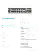

S4112–ON Series installation
To install the S4112-ON Series (S4112F-ON and S4112T-ON) switch, complete the installation procedures in the order presented in this
section.
Always handle the switch and its components with care. Avoid dropping the switch or any eld replaceable units (FRUs).
NOTE: ESD damage can occur if components are mishandled. Always wear an ESD-preventive wrist or heel ground strap when
handling the S4112–ON Series switch and its components. As with all electrical devices of this type, take all the necessary safety
precautions to prevent injury when installing this switch.
NOTE: For more information, see the
Open Networking Hardware Diagnostic Guide
.
Topics:
• Unpack
• Ground cable
• Rack or cabinet installation
• Half RU front-rack installation
• Switch installation
• Optics installation
• Switch power-up
• After switch installation
• Switch replacement
Unpack
NOTE
: Before unpacking the switch, inspect the container and immediately report any evidence of damage.
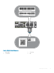
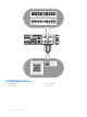
When unpacking the S4112-ON Series switch, make sure that the following items are included:
• One S4112F-ON or S4112T-ON switch
• One RJ-45 to DB-9 female cable
• AC power: two country- and region-specic AC power cables
• Two AC power cable clips
• DC power: two DC connectors
• AC ground lug kit
• DC ground lug kit—included in the accessories box
• S4112–ON Series Set-up Guide
• Safety and Regulatory Information
• Warranty and Support Information
Unpack steps
1 Place the container on a clean, at surface and cut all straps securing the container.
4
20 S4112–ON Series installation