
Install Guide

Management ports
Besides the 10 GbE and 40 GbE switch ports, the S4048T–ON system provides several ports for management and storage.
NOTE: The output examples in this section are for reference only. Your output may vary.
Topics:
• RS-232 console port access
• Micro USB-B console port access
• USB storage mount
RS-232 console port access
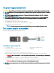
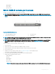
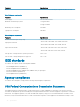
The RS-232 console port is on the PSU-side of the S4048T-ON chassis.
Figure 21. S4048T–ON PSU-side view
1
PSU1 2 Fan modules
3 RS-232/RJ-45 serial console port 4 PSU2
5 10/100/1000BaseT Ethernet management port
CAUTION: Ensure that any equipment attached to the serial port can support the required 115200 baud rate.
NOTE: When connecting the RJ45 console to the patch panel or terminal server using Cat5e or Cat6 Ethernet cables, the
maximum cable length is 100m. However, if the Ethernet cable is disconnected from the patch panel or terminal server but
connected to the RJ45 console, the maximum cable length is 6m. If the cable is longer than 6m when disconnected from the
panel or server, your switch may not boot.
NOTE: Before starting this procedure, be sure that your PC has a 9-pin serial port and you have a terminal emulation program
already installed and running on the PC.
NOTE: If your PC’s serial port cannot accept a female DB-9 connector, use a DB-9 male-to-male adaptor.
1 Install the provided RJ-45 connector side of the provided cable into the console port.
2 Install the DB-9 female side of the provided copper cable into your PC’s serial port or into other data terminal equipment (DTE) server
hardware that you intend to use.
3 Keep the default terminal settings on the console as follows:
• 115200-baud rate
• No parity
8
36 Management ports