Dell EMC S4048T-ON Installation Guide January 2019
Notes, cautions, and warnings NOTE: A NOTE indicates important information that helps you make better use of your computer. CAUTION: A CAUTION indicates either potential damage to hardware or loss of data and tells you how to avoid the problem. WARNING: A WARNING indicates a potential for property damage, personal injury, or death. © 2016 - 2019 Dell Inc. or its subsidiaries. All rights reserved. Dell, EMC, and other trademarks are trademarks of Dell Inc. or its subsidiaries.
Contents 1 About this guide............................................................................................................................................. 5 Related documents............................................................................................................................................................ 5 2 The S4048T-ON System................................................................................................................................6 Introduction.
Grub bootloader exampleONIE example................................................................................................................. 27 ONIE service discovery............................................................................................................................................. 28 6 Power supplies............................................................................................................................................ 30 Components.......................
1 About this guide This guide provides site preparation recommendations, step-by-step procedures for rack mounting and desk mounting, inserting optional modules, and connecting to a power source. CAUTION: To avoid electrostatic discharge (ESD) damage, wear grounding wrist straps when handling this equipment. WARNING: Only trained and qualified personnel can install this equipment. Read this guide before you install and power up this equipment. This equipment contains two power cords.
2 The S4048T-ON System The following sections describe the Dell EMC S4048T-ON system: Topics: • Introduction • System status • LED display • Luggage tag • Prerequisites • S4048T-ON configurations Introduction The S4048T-ON is a networking switch for campus aggregation and core switching 10 Gbps servers and 40 Gbps optical uplinks to the 40 Gbps switching fabric in the core.
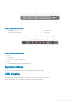
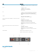
Figure 2. S4048T-ON I/O side view 1 48 10GBase-T ports 2 6 QSFP+ ports 3 Micro USB-B console port 4 USB-A port Figure 3. S4048T-ON PSU-side view 1 PSU1 2 Fan modules 3 RS-232/RJ-45 serial console port 4 PSU2 5 10/100/1000BaseT Ethernet management port System status You can view system status information using the light emitting diodes (LEDs). LED display The S4048T-ON includes LED displays on both the I/O side and PSU side of the chassis.
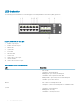
LED behavior The following system LED behavior is seen during open networking installation environment (ONIE) operations: Figure 4. S4048T-ON I/O -side LEDs 1 10 GBT—top row port 2 10 GBT—bottom row port 3 Master LED 4 System LED 5 Power LED 6 Fan status LED 7 Locator LED 8 QSFP+ LED—top row port 9 Stack ID number 10 QSFP+ LED—bottom row port Table 1.
LED Description • Blinking amber—noncritical system error—fan failure or power supply failure Power • • • • Solid green—normal Solid amber—POST is in progress Blinking amber—power supply failed Off—no power Fan • • Solid green—fan powered and running at the expected RPM Blinking amber—fan failed, including incompatible airflow direction when you insert the PSU or fan trays with differing airflows Locator • • Off—locator function is disabled Blinking blue—locator function is enabled QSFP+ port wh
2 Management port link LED 3 PSU LED 4 Management port act LED Table 2.
Luggage tag The S4048T-ON system has a pull-out tag, known as a luggage tag, on the same side as the PSUs. Figure 6. S4048T-ON luggage tag 1 Service tag 2 PPID 3 MAC address 4 Express service code Prerequisites The following is a list of system components: NOTE: For more information, see Site Preparations and S4048T-ON Installation.
• Thread-locker compound—Dell EMC recommends Threadlocker Blue 242 or equivalent • #1 and #2 Phillips screwdrivers • Torx screwdriver • Copper/fiber cables Other optional components are: • Extra fan module, recommended for redundancy • Extra mounting brackets if installing in a four-post rack or cabinet S4048T-ON configurations You can order the S4048T-ON system in several different configurations. Optional modules and optics are available to order separately.
3 Site preparations The S4048T-ON is suitable for installation as part of a common bond network (CBN). You can install the system in: • Network telecommunication facilities • Data centers • Other locations where the National Electric Code (NEC) applies For more information about S4048T-ON specifications, see Specifications. NOTE: Install the S4048T-ON system into a rack or cabinet before installing any optional components.
• Install the switch in Information Technology Rooms in accordance with Article 645 of the National Electrical Code and NFPA 75. For more information about switch storage and environmental temperatures, see Specifications. Review these guidelines for rack mounting: • Rack mounting—You may either place the switch on a rack shelf or mount the switch directly into a 19" wide, EIA-310-E- compliant rack.
Fan combinations Fans are installed as part of the factory install based on SKU type. The system has stock keeping units (SKUs) that support the following configurations: • AC or DC PSU with fan airflow from the I/O to the PSU • AC or DC PSU with fan airflow from the PSU to the I/O Be sure to order the fans suitable to support your site’s ventilation. Use a single type of airflow fan in your system. NOTE: DO NOT mix reverse and normal airflows in a single S4048T-ON chassis.
4 NEBS compliance For your system to be network equipment building system (NEBS) compliant, you must follow the instructions detailed in this chapter. To be NEBs compliant, orient your system in the rack so that the air inlet is from the front aisle and the air exhaust is from the rear aisle.
5 S4048T-ON installation To install the S4048T-ON system, Dell EMC recommends completing the installation procedures in the order presented in this guide. Always handle the S4048T-ON and its components with care. Avoid dropping the system or its field replaceable units (FRUs). NOTE: ESD damage can occur if components are mishandled. Always wear an ESD-preventive wrist or heel ground strap when handling the S4048T-ON and its components.
Ground lug and bracket installation Before you install the system in a rack, install the ground (GND) lug and bracket assembly with a ground wire attached. Dell EMC supplies a kit with the following: • One 2-hole UL-certified GND lug • L-bracket • Two flat head screws to attach the lug to the bracket • Two pan head screws to attach the assembly to the chassis Supply the following: • A wire that complies with your local electrical codes in size and color.
Figure 8. Screws, GND lug, and L-bracket assembly 3 a 1—Flat head screws b 2—GND lug c 3—Attached ground wire Attach the assembly to the S4048T-ON chassis: a b Apply the thread-locker compound to the two pan head screws. Attach the GND lug and bracket assembly to the two-hole chassis ground connector nuts on the PSU side. Tighten the screws to ensure torque between 3–5 inch/lbs.
Figure 9. S4048T-ON PSU-side ground a 1—Pan head screws b 2—L-bracket CAUTION: Take care not to damage the attached ground wire as you proceed to install the switch. After you install the switch in the rack, see Ground wire installation. ReadyRails installation Use the ReadyRails™ rack mounting system to easily configure your rack so that you can install your switch. The ReadyRails system is provided for 1U front-rack and two-post installations.
Align and seat the back flange rail pegs in the back vertical post flange. This illustration shows how the pegs appear in both the square and unthreaded round holes. 2 Align and seat the front flange pegs in the holes on the front side of the vertical post. 3 Repeat this procedure for the second rail. 4 To remove each rail, pull on the latch release button on each flange ear and unseat each rail. Figure 10.
Figure 11. Two-post flush-mount configuration Two-post center-mount configuration CAUTION: Your system is not NEBS Earthquake Z4-compliant if you use this installation method. 1 Slide the plunger bracket rearward until it clicks into place and secure the bracket to the front post flange with two user-supplied screws, item 1. 2 Slide the back bracket towards the post and secure it to the post flange with two user-supplied screws, item 2. 3 Repeat this procedure for the second rail.
Figure 12. Two-post center-mount configuration Four-post threaded configuration CAUTION: To be NEBS Earthquake Z4-compliant, you must remove the tool-less latch castings described in Step 1. 1 Remove the tool-less latch castings from each end of the ReadyRails assemblies. Use a Torx driver to remove the two screws from each latch casting. Remove each casting, item 1. Retain the castings for future rack requirements.
Figure 13. Four-post threaded configuration 1U two-post installation You can install the switch in 1U front-rack, four-post or two-post configurations. The following is an example of a front-rack configuration. For the 1U two-post flush or center configurations, slide the system into the rails in the same manner as the four-post configurations. 1U front-rack installation Configure the rails that are attached to the system: 1 Attach the inner chassis members switch rails to the system, items 1 and 2.
Figure 14. Switch rail attachment 2 After you have installed both switch rails, line them up on the previously mounted Ready-Rails and slide the switch in until it is flush with front of rack. About three inches prior to full insertion, the rail locking feature engages to keep the switch from inadvertently sliding out of the rack and falling. NOTE: Do not the use the mounted Ready-Rails as a shelf or a workplace.
Figure 15. Ground wire and GND lug 1 3 1—Ground wire 2 2—GND lug Install the second GND lug, in compliance with NEC guidelines, at the desired location to ground the switch. a b c Ensure that the rack mating surface is clean. Bring any bare metal to a bright finish. Apply the antioxidant compound to the mating surfaces before mating. Optic installation The S4048T-ON system has 48 RJ-45 ports and six quad small form-factor pluggable plus (QSFP+) optical ports.
Optic removal Remove an optic by pushing the tab on the optic and sliding the optic from the port. When removing optics with direct attach cables (DACs) from the port, pull the release tab firmly and steadily. Before pulling the release tab, you may need to gently push the optic into the port to ensure it is seated properly. Do not jerk or tug repeatedly on the tab. Split ports The S4048T-ON supports splitting a single 40G QSFP+ port into four 10G ports using one of the supported breakout cables.
| ONIE: Rescue | | ONIE: Uninstall OS | | ONIE: Update ONIE | | ONIE: Embed ONIE | | ONIE: Diag ONIE | | | | | | | | | | | | | +----------------------------------------------+ Your system comes with ONIE installed.
The following is an example of the ifconfig eth0 command. ONIE:/ # ifconfig eth0 eth0 Link encap:Ethernet HWaddr 90:B1:1C:F4:9C:76 inet addr:10.11.53.33 Bcast:10.255.255.255 Mask:255.0.0.0 inet6 addr: fe80::92b1:1cff:fef4:9c76/64 Scope:Link UP BROADCAST RUNNING MULTICAST MTU:1500 Metric:1 RX packets:18 errors:0 dropped:0 overruns:0 frame:0 TX packets:24 errors:0 dropped:0 overruns:0 carrier:0 collisions:0 txqueuelen:1000 RX bytes:1152 (1.1 KiB) TX bytes:6864 (6.
6 Power supplies The S4048T-ON ships with two power supply units. The system supports AC or DC power supplies with two air-flow directions—from the I/O side to the PSU side and from the PSU side to the I/O side. Two PSUs are required for full redundancy, but the system can operate with a single PSU. The PSUs are field replaceable. When running with full redundancy—two power supply units installed and running, you can remove and replace one PSU without disrupting traffic.
3 RS-232/RJ-45 serial console port 5 10/100/1000BaseT Ethernet management port 4 PSU2 The PSUs are single units that include an integrated fan. You can individually replace the separate fan units however if the integrated PSU fan fails, you must replace the entire PSU. For fan tray replacement procedures, see Fans. WARNING: Prevent exposure and contact with hazardous voltages. Do not attempt to operate this system with the safety cover removed.
AC power supply replacement CAUTION: Disconnect the power cord before removing the power supplies. Also, disconnect all power cords before servicing. NOTE: The PSU slides into the slot smoothly. Do not force a PSU into a slot as this action may damage the PSU or the S4048T– ON chassis. NOTE: If a PSU fails, you must replace the entire unit. There are no field serviceable components in the PSU. To request a hardware replacement, see Dell Support.
7 Fans The S4048T-ON comes from the factory with two PSUs and four fan modules installed in the chassis. The fan modules and the power supplies, which have integrated fans, are hot-swappable. NOTE: To run the system, the four fan slots must have operating fan units. If you do not install a module in each slot, the system shuts down in one minute. In addition to the power supply modules, you can order and install fan modules separately. The system supports two airflow direction options.
Figure 19. S4048T-ON PSU-side view 1 PSU1 2 Fan modules 3 RS-232/RJ-45 serial console port 4 PSU2 5 10/100/1000BaseT Ethernet management port Fan module installation The fan modules in the S4048T-ON are field replaceable. Module slot 1 is on the left side of the chassis, module slot 2 is in the middle of the chassis, and module slot 3 is on the right side of the chassis. CAUTION: DO NOT mix airflow directions. All fans must use the same airflow direction—reverse or normal.
Fan air filter replacement Environmental factors can decrease the amount of time required between air filter replacements. Check the environmental factors regularly. An increase in temperature and/or particulate matter in the air might affect performance. CAUTION: Check the fan air filters at six-month intervals and replace them as necessary. To accurately determine air filter replacement intervals, regularly monitor the speeds of the cooling fans.
8 Management ports Besides the 10 GbE and 40 GbE switch ports, the S4048T–ON system provides several ports for management and storage. NOTE: The output examples in this section are for reference only. Your output may vary. Topics: • RS-232 console port access • Micro USB-B console port access • USB storage mount RS-232 console port access The RS-232 console port is on the PSU-side of the S4048T-ON chassis. Figure 21.
• Eight data bits • One stop bit • No flow control Micro USB-B console port access The Micro USB-B console port is on the I/O side of the switch. NOTE: The S4048T-ON switch uses the Silicon Labs CP2109 USB-B chip. To find the correct USB-B universal asynchronous receiver-transmitter (UART) driver, see https://www.silabs.com/products/development-tools/software/usb-to-uart-bridge-vcpdrivers. Figure 22.
USB storage mount The USB storage supports the FAT file system. The USB storage does not automatically mount. To use USB storage, you must first mount the device. 1 Create a mount directory for the USB. ONIE:/ # mkdir /mnt/usb 2 View the fixed disks using the fdisk command. ONIE:/mnt # fdisk -l For internal storage: Disk /dev/sda: 15.
9 Specifications This chapter lists the S4048T–ON specifications. CAUTION: Operate the product at an ambient temperature not higher than 113°F (45°C). CAUTION: Lithium Battery Caution: There is a danger of explosion if the battery is incorrectly replaced. Replace only with same or equivalent type of battery. Dispose of the batteries according to the manufacturer's instructions. NOTE: For RoHS information, see Restricted Material Compliance.
Parameter Specifications Shock Meets Bellcore Zone 4 earthquake requirements, MIL-STD-810. Table 5. AC power requirements Parameter Specifications Power supply 100–240 VAC 50/60 Hz. Maximum current draw per system 7.1 A @ 550 Watts 3.4 A @ 550 Watts Maximum power consumption 550 Watts. Typical power consumption 338 Watts. Table 6. DC power requirements Parameter Specifications Minimum/maximum input voltage range -40.5V/ -48V/ -60V Input power at full load −40.
harmful interference, in which case users will be required to take whatever measures necessary to correct the interference at their own expense. Properly shielded and grounded cables and connectors must be used in order to meet FCC emission limits. Dell EMC is not responsible for any radio or television interference caused by using other than recommended cables and connectors or by unauthorized changes or modifications in the equipment.
Figure 25. Japan: Warning Label Korean Certification of Compliance Figure 26. Korean Certification of Compliance Figure 27.
• EN 60825-2 Safety of Laser Products — Part 2: Safety of Optical Fibre Communication Systems • FDA Regulation 21CFR 1040.10 and 1040.11 • IEC 60950-1, 2nd Ed, including all National Deviations and Group Differences Electromagnetic Compatibility Emissions • International: CISPR 22, Class A • Australia/New Zealand: AS/NZS CISPR 22, Class A • Canada: ICES-003, Issue-4, Class A • Europe: EN55022 2006 (CISPR 22), Class A • Japan: VCCI V-3/2011.
Figure 28. The European WEEE Symbol In accordance with the European WEEE Directive, electrical and electronic equipment (EEE) is to be collected separately and to be reused, recycled, or recovered at end of life. Users of EEE with the WEEE marking per Annex IV of the WEEE Directive, as shown above, must not dispose of end of life EEE as unsorted municipal waste, but use the collection framework available to customers for the return, recycling and recovery of WEEE.
10 Dell EMC support The Dell EMC support site provides a range of documents and tools to assist you with using Dell EMC equipment and mitigating the impact of network outages. Through the support site you can obtain technical information regarding Dell EMC products, access software upgrades and patches, download available management software, and manage your open cases. The Dell EMC support site provides integrated, secure access to these services. To access the Dell EMC support site, go to www.dell.