
Install Guide
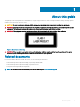
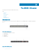
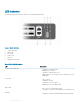
Table Of Contents
- S3048-ON Installation Guide January 2019
- About this guide
- The S3048–ON switch
- Site preparations
- NEBS compliance
- Install the S3048–ON
- Power supplies
- Fans
- Management ports
- Specifications
- Chassis physical design
- IEEE Standards
- Agency compliance
- USA Federal Communications Commission Statement
- European Union EMC Directive Conformance Statement
- Japan VCCI Compliance for Class A Equipment
- Korean Certification of Compliance
- Safety Standards and Compliance Agency Certifications
- Electromagnetic compatibility
- Product recycling and disposal
- Dell EMC support

LED Description
• Solid yellow—Fan failed including incompatible airow direction
when you insert the PSU or fan trays with diering airows
LOCATOR LED
• O—Locator function is disabled
• Blinking blue—Locator function is enabled
Table 2. Management Ethernet port LEDs
LED Description
Link LED
• O—No link
• Solid green—Link on 1 Gbps speed
• Solid yellow—Link on 10/100 Mbps speeds
Table 3. SFP+ Port LEDs
LED Description
Link LED
• O—No link
• Solid green—Link on 10 Gbps speed
• Flashing green, ~1 s—Link on less than 10 G speed
Activity LED
• O—No link
• Flashing green, ~30 ms—10 Gbps activity
• Flashing green, ~1 s—Specic port locate
Prerequisites
The following is a list of components required for successful installation of the S3048-ON:
NOTE
: Detailed installation instructions for the S3048-ON are provided in Site Preparations and Install the S3048–ON.
• S3048–ON chassis or multiple chassis, if stacking
• AC country/regional-specic cables to connect the AC power source to each of the chassis’ AC power supplies
• Mounting brackets for rack installation, included
• Screws for rack installation
• #1 and #2 Phillips screw drivers, not included
• Torx screwdriver, not included
• Ground cable screws, included
• Copper/ber cables
Other optional components are:
• Ground cable
• Extra power supply unit
• Extra fan module
• Extra mounting brackets if installing in a four-post rack or cabinet
The S3048–ON switch
9