
Install Guide
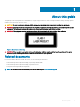
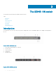
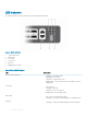
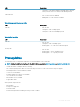
Table Of Contents
- S3048-ON Installation Guide January 2019
- About this guide
- The S3048–ON switch
- Site preparations
- NEBS compliance
- Install the S3048–ON
- Power supplies
- Fans
- Management ports
- Specifications
- Chassis physical design
- IEEE Standards
- Agency compliance
- USA Federal Communications Commission Statement
- European Union EMC Directive Conformance Statement
- Japan VCCI Compliance for Class A Equipment
- Korean Certification of Compliance
- Safety Standards and Compliance Agency Certifications
- Electromagnetic compatibility
- Product recycling and disposal
- Dell EMC support
LED behavior
The following S3048–ON switch LED behavior is seen during ONIE operations:
Figure 4. S3048–ON LEDs
1 System Status LED
2 Master LED
3 Power LED
4 Locator LED
5 Fan LED
6 Management Port LEDs
Table 1. S3048–ON LED behavior
LED Description
System Status/Health LED
• Solid green—Normal operation
• Blinking green—Booting
• Solid yellow—Critical system error
• Blinking yellow—Non-critical system error, fan failure, or power
supply failure
Power LED
• O—No power
• Solid Green—Normal
• Solid yellow—POST is in process
• Blinking yellow—Power supply failed
Master LED
• O—Switch is in Stacking Slave mode
• Solid green—System is in Stacking Master or Standalone mode
FAN LED
• Solid green—Fan powered and running at the expected RPM
8 The S3048–ON switch