
Deployment Guide

16 VCF on VxRail Multirack Deployment using BGP EVPN
4 Topology
4.1 Leaf-spine underlay
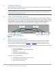
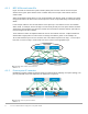
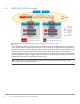
In a Layer 3 leaf-spine network, the traffic between leaf switches and spine switches are routed. Equal cost
multipath routing (ECMP) is used to load balance traffic across the Layer 3 connections. BGP is used to
exchange routes. The Layer 3/Layer 2 (L3/L2) boundary is at the leaf switches.
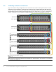
Two leaf switches are configured as Virtual Link Trunking (VLT) peers at the top of each rack. VLT allows all
connections to be active while also providing fault tolerance. As administrators add racks to the data center,
two leaf switches configured for VLT are added to each new rack. Connections within racks from hosts to leaf
switches are Layer 2, and each host is connected using a VLT port-channel.
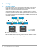
In this example, two Z9264F-ON switches are used as spines, and four S5248F-ON switches are used as leaf
switches in Rack 1 and Rack 2.
Rack 2Rack 1
Leaf02B
Leaf02A
VLTi
Leaf01B
Leaf01A
VLTi
Spine 1 Spine 2
Spine01 Spine02
L3 Connection
L3
L2
VxRail Node VxRail Node
ECMP
L2 Connection
VxRail Node
VxRail Node
Leaf-spine underlay network
Note: Using a leaf-spine network in the data center is considered a best practice. With Z9264F-ON switches
as spines and two leaf switches per rack, this topology scales to 32 racks. For more leaf-spine network
information, see Dell EMC PowerSwitch Layer 3 Leaf-Spine Deployment and Best Practices with OS10.
There are some BGP configuration differences in this guide to enable the BGP EVPN VXLAN feature.