
Deployment Guide

15 VCF on VxRail Multirack Deployment using BGP EVPN
3.2.1 The VXLAN protocol
VXLAN allows a Layer 2 network to scale across the data center by overlaying an existing Layer 3 network
and is described in Internet Engineering Task Force document RFC 7348. Each overlay is seen as a VXLAN
segment.
Each segment is identified through a 24-bit segment ID seen as a VNI. This allows up to 16 Million VNIs, far
more than the traditional 4,094 VLAN IDs that are allowed on a physical switch.
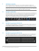
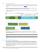
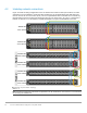
VXLAN is a tunneling scheme that encapsulates Layer 2 frames in User Datagram Protocol (UDP) segments,
as shown in Figure 10.
VXLAN encapsulated frame
VXLAN encapsulation adds approximately 50 bytes of overhead to each Ethernet frame. As a result, all
switches in the underlay (physical) network must be configured to support an MTU of at least 1600 bytes on
all participating interfaces.
Note: In this deployment example, switch interfaces are set to their maximum supported MTU size of 9216
bytes.
VTEPs handle VXLAN encapsulation and de-encapsulation. In this implementation, the leaf switches are the
VTEPs.
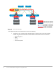
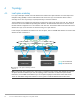
3.2.2 BGP EVPN VXLAN operation
EVPN uses BGP to exchange endpoint MAC and IP address information between VTEPs. When a host
sends a packet to an endpoint, the switch looks up the routing table for a match. If it finds a match that exists
behind another VTEP, the packet is encapsulated with VXLAN and UDP headers and encapsulated again
with outer IP and Ethernet headers for transport over the leaf-spine network. When the packet arrives at the
destination VTEP, the outer Ethernet, IP, UDP, and VXLAN headers are removed, and the switch sends the
original packet to the endpoint.