
Users Guide
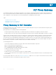

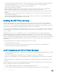
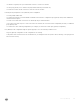


Figure 123. Example of VLT Deployment
VLT on Core Switches
Uplinks from servers to the access layer and from access layer to the aggregation layer are bundled in LAG groups with end-to-end Layer 2
multipathing. This set up requires “horizontal” stacking at the access layer and VLT at the aggregation layer such that all the uplinks from
servers to access and access to aggregation are in Active-Active Load Sharing mode. This example provides the highest form of resiliency,
scaling, and load balancing in data center switching networks.
The following example shows stacking at the access, VLT in aggregation, and Layer 3 at the core.
The aggregation layer is mostly in the L2/L3 switching/routing layer. For better resiliency in the aggregation, Dell Networking recommends
running the internal gateway protocol (IGP) on the VLTi VLAN to synchronize the L3 routing table across the two nodes on a VLT system.
Enhanced VLT
An enhanced VLT (eVLT) conguration creates a port channel between two VLT domains by allowing two dierent VLT domains, using
dierent VLT domain ID numbers, connected by a standard link aggregation control protocol (LACP) LAG to form a loop-free Layer 2
topology in the aggregation layer.
This conguration supports a maximum of four switches, increasing the number of available ports and allowing for dual redundancy of the
VLT. The following example shows how the core/aggregation port density in the Layer 2 topology is increased using eVLT. For inter-VLAN
routing and other Layer 3 routing, you need a separate Layer 3 router.
Virtual Link Trunking (VLT)
819