
Deployment Guide

27 Dell EMC Networking Virtualization Overlay with BGP EVPN
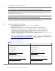
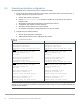
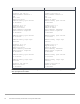
Route map configuration
Leaf1a
Leaf1b
route-map spine-leaf permit 10
match ip address prefix-list spine-
leaf
ip prefix-list spine-leaf seq 20
permit 10.2.2.0/24 ge 32
ip prefix-list spine-leaf seq 30
permit 10.222.222.0/24 ge 32
route-map spine-leaf permit 10
match ip address prefix-list spine-
leaf
ip prefix-list spine-leaf seq 20
permit 10.2.2.0/24 ge 32
ip prefix-list spine-leaf seq 30
permit 10.222.222.0/24 ge 32
Note: The remaining leaf switches are configured with identical settings to those shown above in this
deployment example.
6.8 Configure UFD in reverse
Uplink Failure Detection (UFD) shuts down ports marked as downstream ports if all ports marked as upstream
ports go down. To reduce traffic loss when a VLT peer boots up and joins an existing VLT domain, or if all
VLTi links fail while the VLT peer is still up as detected by the VLT heartbeat, create an uplink state group in
reverse.
For example, if all VLTi links fail while the heartbeat is still up, VLT shuts down the server-connected VLT port
channels on the secondary VLT peer. Without reverse UFD, spines continue to route traffic to both VLT peers
and half of the traffic (that sent to the secondary peer) is lost. With reverse UFD, the ports connected to the
spines on the secondary peer will also be shut down in response to the VLT port channels going down. This
ensures spines send all traffic to the VLT primary peer until at least one VLTi link is restored.
To configure reverse UFD, the downstream server-connected VLT port channels are configured as upstream
ports, and the upstream ports connected to the spines are configured as downstream ports.
1. Create an uplink state group.
2. Add "upstream" port channels connected to servers.
3. Add "downstream" interfaces connected to spines.
4. Enable the uplink state group.
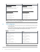
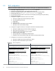
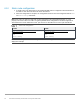
Configure UFD in reverse
Leaf1a
Leaf1b
uplink-state-group 1
upstream port-channel100
upstream port-channel101
downstream ethernet1/1/53
downstream ethernet1/1/54
enable
uplink-state-group 1
upstream port-channel100
upstream port-channel101
downstream ethernet1/1/53
downstream ethernet1/1/54
enable
Note: The remaining leaf switches are configured in the same manner. Upstream ports are the server-
connected VLT port channels ports for Leafs 1a, 1b, 2a, and 2b, and the gateway/firewall connected port
channel for Leafs 3a and 3b. S4148U-ON leaf switches use different downstream ports, ethernet 1/1/25-
1/1/26, for the 100GbE connections to the spines.