
Deployment Guide

14 Dell EMC Networking Virtualization Overlay with BGP EVPN
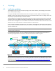
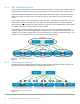
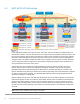
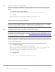
Each link is a separate, point-to-point IP network. Table 1 details the links labeled in Figure 10. The IP
addresses in the table are used in the switch configuration examples.
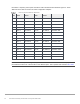
Point-to-point network IP addresses
Link
label
Source
switch
Source IP
address
Destination
switch
Destination IP
address
Network
A
Spine 1
192.168.1.0
Leaf 1a
192.168.1.1
192.168.1.0/31
B
Spine 2
192.168.2.0
Leaf 1a
192.168.2.1
192.168.2.0/31
C
Spine 1
192.168.1.2
Leaf 1b
192.168.1.3
192.168.1.2/31
D
Spine 2
192.168.2.2
Leaf 1b
192.168.2.3
192.168.2.2/31
E
Spine 1
192.168.1.4
Leaf 2a
192.168.1.5
192.168.1.4/31
F
Spine 2
192.168.2.4
Leaf 2a
192.168.2.5
192.168.2.4/31
G
Spine 1
192.168.1.6
Leaf 2b
192.168.1.7
192.168.1.6/31
H
Spine 2
192.168.2.6
Leaf 2b
192.168.2.7
192.168.2.6/31
I
Spine 1
192.168.1.8
Leaf 3a
192.168.1.9
192.168.1.8/31
J
Spine 2
192.168.2.8
Leaf 3a
192.168.2.9
192.168.2.8/31
K
Spine 1
192.168.1.10
Leaf 3b
192.168.1.11
192.168.1.10/31
L
Spine 2
192.168.2.10
Leaf 3b
192.168.2.11
192.168.2.10/31
M
Leaf 1a
192.168.3.0
Leaf 1b
192.168.3.1
192.168.3.0/31
N
Leaf 2a
192.168.3.2
Leaf 2b
192.168.3.3
192.168.3.2/31
O
Leaf 3a
192.168.3.4
Leaf 3b
192.168.3.5
192.168.3.4/31
Note: As with all examples in this guide, any valid IP address scheme can be used. The example point-to-
point addresses above use a 31-bit mask to save address space. This is optional and covered in RFC 3021.