
Deployment Guide

13 Dell EMC Networking Virtualization Overlay with BGP EVPN
4.1.1 BGP ASNs and router IDs
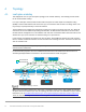
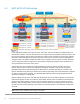
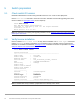
Figure 9 shows the autonomous system numbers (ASNs) and router IDs used for the leaf and spine switches
in this guide. Spine switches share a common ASN and each pair of leaf switches shares a common ASN.
ASNs should follow a logical pattern for ease of administration and allow for growth as switches are added.
Using private ASNs in the data center is a best practice. Private, 2-byte ASNs range from 64512 through
65534.
In this example, 65101 is used on both switches at the spine layer. Leaf switches use ASNs with a "2" in the
hundreds place, 65201 for example, and the last digit is used to uniquely identify the leaf pair. Additional
spine switches would be assigned the existing ASN for the spine layer, 65101. Additional leaf switches would
be added in pairs with the next pair assigned an ASN of 65204.
The IP addresses shown are loopback addresses used as BGP router IDs and for BGP EVPN peering.
Loopback addresses should follow a logical pattern to make it easier to manage and allow for growth. In this
example, the 10.2.0.0/16 IP address space is used. The third octet in the address represents the layer, “1” for
spine and “2” for leaf, and the fourth octet is the counter for the appropriate layer
AS65202AS65201
10.2.2.4
10.2.2.3
VLTi
10.2.2.2
10.2.2.1
VLTi
AS65203
10.2.2.6
10.2.2.5
VLTi
Spine 1 Spine 210.2.1.1 10.2.1.2
AS 65101
BGP ASNs and router IDs
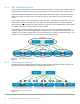
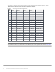
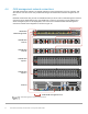
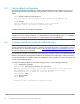
4.1.2 Point-to-point IP networks
Establishing a logical, scalable IP address scheme is important before deploying a leaf-spine topology. The
point-to-point links used in this deployment are labeled A-O in Figure 10.
Rack 2Rack 1
Leaf 2b
Leaf 2a
VLTi
Leaf 1b
Leaf 1a
VLTi
Rack n
Leaf 3b
Leaf 3a
VLTi
Spine 1 Spine 2Spine 1 Spine 2
BA FEDC G IH J K L
M
N
O
Point-to-point networks