
Users Guide
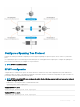
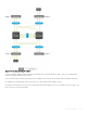
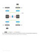
Table Of Contents
- Dell EMC SmartFabric OS10 User Guide Release 10.5.0
- Change history
- Getting Started
- CLI Basics
- CONFIGURATION mode
- Check device status
- Command help
- Candidate configuration
- Copy running configuration
- Restore startup configuration
- Reload system image
- Filter show commands
- Common OS10 commands
- boot
- commit
- configure
- copy
- delete
- dir
- discard
- do
- end
- exit
- hostname
- license
- lock
- management route
- move
- no
- ping
- ping6
- reload
- show boot
- show candidate-configuration
- show environment
- show inventory
- show ip management-route
- show ipv6 management-route
- show license status
- show running-configuration
- show startup-configuration
- show system
- show version
- start
- system
- system-cli disable
- system-user linuxadmin disable
- system identifier
- terminal
- traceroute
- unlock
- username password role
- write
- Advanced CLI tasks
- Zero-touch deployment
- OS10 provisioning
- System management
- Interfaces
- Ethernet interfaces
- Unified port groups
- Z9264F-ON port-group profiles
- Port-groups on S5200F-ON switches
- L2 mode configuration
- L3 mode configuration
- Fibre Channel interfaces
- Management interface
- VLAN interfaces
- User-configured default VLAN
- VLAN scale profile
- Loopback interfaces
- Port-channel interfaces
- Configure interface ranges
- Switch-port profiles
- Configure negotiation modes on interfaces
- Configure breakout mode
- Breakout auto-configuration
- Reset default configuration
- Forward error correction
- Energy-efficient Ethernet
- View interface configuration
- Digital optical monitoring
- Interface commands
- channel-group
- default interface
- default vlan-id
- description (Interface)
- duplex
- enable dom
- enable dom traps
- feature auto-breakout
- fec
- interface breakout
- interface ethernet
- interface loopback
- interface mgmt
- interface null
- interface port-channel
- interface range
- interface vlan
- link-bundle-utilization
- mode
- mode l3
- mtu
- negotiation
- port mode Eth
- port-group
- profile
- scale-profile vlan
- show interface
- show interface transceiver “Tunable wavelength”
- show inventory media
- show link-bundle-utilization
- show port-channel summary
- show port-group
- show switch-port-profile
- show system
- show vlan
- shutdown
- speed (Fibre Channel)
- speed (Management)
- switch-port-profile
- switchport access vlan
- switchport mode
- switchport trunk allowed vlan
- wavelength
- Fibre Channel
- Fibre Channel over Ethernet
- Terminology
- Virtual fabric
- Fibre Channel zoning
- F_Port on Ethernet
- Pinning FCoE traffic to a specific port of a port-channel
- Multi-hop FIP-snooping bridge
- Configuration guidelines
- NPIV Proxy Gateway cascading
- F_Port commands
- NPG commands
- F_Port and NPG commands
- FIP-snooping commands
- FCoE commands
- Layer 2
- 802.1X
- Far-end failure detection
- Link Aggregation Control Protocol
- Link Layer Discovery Protocol
- Protocol data units
- Optional TLVs
- Organizationally-specific TLVs
- Media endpoint discovery
- Network connectivity device
- LLDP-MED capabilities TLV
- Network policies TLVs
- Define network policies
- Packet timer values
- Disable and re-enable LLDP
- Disable and re-enable LLDP on management ports
- Advertise TLVs
- Network policy advertisement
- Fast start repeat count
- View LLDP configuration
- Adjacent agent advertisements
- Time to live
- LLDP commands
- Media Access Control
- Spanning-tree protocol
- Virtual LANs
- Port monitoring
- Layer 3
- Virtual routing and forwarding
- Bidirectional Forwarding Detection
- Border Gateway Protocol
- Sessions and peers
- Route reflectors
- Multiprotocol BGP
- Attributes
- Selection criteria
- Weight and local preference
- Multiexit discriminators
- Origin
- AS path and next-hop
- Best path selection
- More path support
- Advertise cost
- 4-Byte AS numbers
- AS number migration
- Graceful restart
- Configure Border Gateway Protocol
- Enable BGP
- Configure Dual Stack
- Configure administrative distance
- Peer templates
- Neighbor fall-over
- Configure password
- Fast external fallover
- Passive peering
- Local AS
- AS number limit
- Redistribute routes
- Additional paths
- MED attributes
- Local preference attribute
- Weight attribute
- Enable multipath
- Route-map filters
- Route reflector clusters
- Aggregate routes
- Confederations
- Route dampening
- Timers
- Neighbor soft-reconfiguration
- Redistribute iBGP route to OSPF
- Debug BGP
- BGP commands
- Equal cost multi-path
- IPv4 routing
- IPv6 routing
- Open shortest path first
- Object tracking manager
- Policy-based routing
- Policy-based route-maps
- Access-list to match route-map
- Set address to match route-map
- Assign route-map to interface
- View PBR information
- Policy-based routing per VRF
- Configuring PBR per VRF
- Sample configuration
- Track route reachability
- Use PBR to permit and block specific traffic
- View PBR configuration
- PBR commands
- Virtual Router Redundancy Protocol
- Multicast
- VXLAN
- VXLAN concepts
- VXLAN as NVO solution
- Configure VXLAN
- L3 VXLAN route scaling
- DHCP relay on VTEPs
- View VXLAN configuration
- VXLAN MAC addresses
- VXLAN commands
- hardware overlay-routing-profile
- interface virtual-network
- ip virtual-router address
- ip virtual-router mac-address
- member-interface
- nve
- remote-vtep
- show hardware overlay-routing-profile mode
- show interface virtual-network
- show nve remote-vtep
- show nve remote-vtep counters
- show nve vxlan-vni
- show virtual-network
- show virtual-network counters
- show virtual-network interface counters
- show virtual-network interface
- show virtual-network vlan
- show vlan (virtual network)
- source-interface loopback
- virtual-network
- virtual-network untagged-vlan
- vxlan-vni
- VXLAN MAC commands
- clear mac address-table dynamic nve remote-vtep
- clear mac address-table dynamic virtual-network
- show mac address-table count extended
- show mac address-table count nve
- show mac address-table count virtual-network
- show mac address-table extended
- show mac address-table nve
- show mac address-table virtual-network
- Example: VXLAN with static VTEP
- BGP EVPN for VXLAN
- BGP EVPN compared to static VXLAN
- VXLAN BGP EVPN operation
- Configure BGP EVPN for VXLAN
- VXLAN BGP EVPN routing
- BGP EVPN with VLT
- VXLAN BGP commands
- VXLAN EVPN commands
- Example: VXLAN with BGP EVPN
- Example: VXLAN with BGP EVPN — Multi-AS Topology
- Example: Centralized Layer3 gateway routing
- Example: Border Leaf Gateway
- Controller-provisioned VXLAN
- UFT modes
- Security
- User re-authentication
- Password strength
- Simple password check
- Obscure passwords
- Role-based access control
- Assign user role
- Bootloader protection
- Linuxadmin user configuration
- RADIUS authentication
- RADIUS over TLS authentication
- TACACS+ authentication
- Unknown user role
- SSH server
- Virtual terminal line ACLs
- Restrict SNMP access
- Enable AAA accounting
- Enable user lockout
- Limit concurrent login sessions
- Enable login statistics
- Privilege levels
- Audit log
- Security commands
- aaa accounting
- aaa authentication login
- aaa re-authenticate enable
- boot protect disable username
- boot protect enable username password
- clear logging audit
- crypto ssh-key generate
- disable
- enable
- enable password priv-lvl
- ip access-class
- ip radius source-interface
- ip tacacs source-interface
- ipv6 access-class
- ip ssh server challenge-response-authentication
- ip ssh server cipher
- ip ssh server enable
- ip ssh server hostbased-authentication
- ip ssh server kex
- ip ssh server mac
- ip ssh server password-authentication
- ip ssh server port
- ip ssh server pubkey-authentication
- ip ssh server vrf
- line vty
- logging audit enable
- login concurrent-session limit
- login-statistics enable
- password-attributes
- password-attributes max-retry lockout-period
- privilege
- radius-server host
- radius-server host tls
- radius-server retransmit
- radius-server timeout
- radius-server vrf
- service obscure-password
- service simple-password
- show boot protect
- show crypto ssh-key
- show ip ssh
- show logging audit
- show login-statistics
- show privilege
- show running-configuration privilege
- show users
- system-user linuxadmin disable
- system-user linuxadmin password
- tacacs-server host
- tacacs-server timeout
- tacacs-server vrf
- username password role
- username sshkey
- username sshkey filename
- userrole inherit
- X.509v3 certificates
- OpenFlow
- Access Control Lists
- IP ACLs
- MAC ACLs
- Control-plane ACLs
- IP fragment handling
- L3 ACL rules
- Assign sequence number to filter
- Delete ACL rule
- L2 and L3 ACLs
- Assign and apply ACL filters
- Ingress ACL filters
- Egress ACL filters
- VTY ACLs
- SNMP ACLs
- Clear access-list counters
- IP prefix-lists
- Route-maps
- Match routes
- Set conditions
- Continue clause
- ACL flow-based monitoring
- Enable flow-based monitoring
- View ACL table utilization report
- ACL logging
- ACL commands
- clear ip access-list counters
- clear ipv6 access-list counters
- clear mac access-list counters
- deny
- deny (IPv6)
- deny (MAC)
- deny icmp
- deny icmp (IPv6)
- deny ip
- deny ipv6
- deny tcp
- deny tcp (IPv6)
- deny udp
- deny udp (IPv6)
- description
- ip access-group
- ip access-list
- ip as-path access-list
- ip community-list standard deny
- ip community–list standard permit
- ip extcommunity-list standard deny
- ip extcommunity-list standard permit
- ip prefix-list description
- ip prefix-list deny
- ip prefix-list permit
- ip prefix-list seq deny
- ip prefix-list seq permit
- ipv6 access-group
- ipv6 access-list
- ipv6 prefix-list deny
- ipv6 prefix-list description
- ipv6 prefix-list permit
- ipv6 prefix-list seq deny
- ipv6 prefix-list seq permit
- mac access-group
- mac access-list
- permit
- permit (IPv6)
- permit (MAC)
- permit icmp
- permit icmp (IPv6)
- permit ip
- permit ipv6
- permit tcp
- permit tcp (IPv6)
- permit udp
- permit udp (IPv6)
- remark
- seq deny
- seq deny (IPv6)
- seq deny (MAC)
- seq deny icmp
- seq deny icmp (IPv6)
- seq deny ip
- seq deny ipv6
- seq deny tcp
- seq deny tcp (IPv6)
- seq deny udp
- seq deny udp (IPv6)
- seq permit
- seq permit (IPv6)
- seq permit (MAC)
- seq permit icmp
- seq permit icmp (IPv6)
- seq permit ip
- seq permit ipv6
- seq permit tcp
- seq permit tcp (IPv6)
- seq permit udp
- seq permit udp (IPv6)
- show access-group
- show access-lists
- show acl-table-usage detail
- show ip as-path-access-list
- show ip community-list
- show ip extcommunity-list
- show ip prefix-list
- show logging access-list
- Route-map commands
- continue
- match as-path
- match community
- match extcommunity
- match interface
- match ip address
- match ip next-hop
- match ipv6 address
- match ipv6 next-hop
- match metric
- match origin
- match route-type
- match tag
- route-map
- set comm-list add
- set comm-list delete
- set community
- set extcomm-list add
- set extcomm-list delete
- set extcommunity
- set local-preference
- set metric
- set metric-type
- set next-hop
- set origin
- set tag
- set weight
- show route-map
- Quality of service
- Configure quality of service
- Ingress traffic classification
- Egress traffic classification
- Policing traffic
- Mark Traffic
- Color traffic
- Modify packet fields
- Shaping traffic
- Bandwidth allocation
- Strict priority queuing
- Rate adjustment
- Buffer management
- Congestion avoidance
- Storm control
- RoCE for faster access and lossless connectivity
- Port to port-pipe and MMU mapping
- QoS commands
- bandwidth
- buffer-statistics-tracking
- class
- class-map
- clear qos statistics
- clear qos statistics type
- control-plane
- control-plane-buffer-size
- flowcontrol
- hardware deep-buffer-mode
- match
- match cos
- match dscp
- match precedence
- match queue
- match vlan
- mtu
- pause
- pfc-cos
- pfc-max-buffer-size
- pfc-shared-buffer-size
- pfc-shared-headroom-buffer-size
- police
- policy-map
- priority
- priority-flow-control mode
- qos-group dot1p
- qos-group dscp
- qos-rate-adjust
- queue-limit
- queue bandwidth
- queue qos-group
- random-detect (interface)
- random-detect (queue)
- random-detect color
- random-detect ecn
- random-detect ecn
- random-detect pool
- random-detect weight
- service-policy
- set cos
- set dscp
- set qos-group
- shape
- show class-map
- show control-plane buffers
- show control-plane buffer-stats
- show control-plane info
- show control-plane statistics
- show hardware deep-buffer-mode
- show interface priority-flow-control
- show qos interface
- show policy-map
- show qos control-plane
- show qos egress bufffers interface
- show qos egress buffer-statistics-tracking
- show qos egress buffer-stats interface
- show qos headroom-pool buffer-statistics-tracking
- show qos ingress buffers interface
- show qos ingress buffer-statistics-tracking
- show qos ingress buffer-stats interface
- show qos port-map details
- show qos-rate-adjust
- show qos service-pool buffer-statistics-tracking
- show qos system
- show qos system buffers
- show qos maps
- show qos wred-profile
- show queuing statistics
- system qos
- trust-map
- trust dot1p-map
- trust dscp-map
- qos-map traffic-class
- trust-map
- wred
- Virtual Link Trunking
- Terminology
- VLT domain
- VLT interconnect
- Graceful LACP with VLT
- Configure VLT
- Configure VRRP Active-Active mode
- Migrate VMs across data centers with eVLT
- View VLT information
- VLT commands
- backup destination
- delay-restore
- discovery-interface
- peer-routing
- peer-routing-timeout
- primary-priority
- show running-configuration vlt
- show spanning-tree virtual-interface
- show vlt
- show vlt backup-link
- show vlt mac-inconsistency
- show vlt mismatch
- show vlt role
- show vlt vlt-port-detail
- vlt-domain
- vlt-port-channel
- vlt-mac
- vrrp mode active-active
- Uplink Failure Detection
- Converged data center services
- sFlow
- Telemetry
- Telemetry terminology
- YANG-modeled telemetry data
- Configure telemetry
- View telemetry configuration
- Telemetry commands
- debug telemetry
- destination
- destination-group (subscription-profile)
- destination-group (telemetry)
- enable
- encoding
- gnmi-security-profile
- sensor-group (subscription-profile)
- sensor-group (telemetry)
- sensor-path
- show telemetry
- show switch-operating-mode
- source interface
- subscription-profile
- switch-operating mode
- telemetry
- transport
- Example: Configure streaming telemetry
- RESTCONF API
- Troubleshoot OS10
- Support resources

NOTE: To view all other ports, use the show spanning-tree active command.
View STP virtual interface detail
OS10# show spanning-tree virtual-interface detail
Port 1 (VFP(VirtualFabricPort)) of RSTP 1 is designated Forwarding
Port path cost 1, Port priority 0, Port Identifier 0.1
Designated root priority: 32768, address: 00:78:76:14:60:62
Designated bridge priority: 32768, address: 00:78:76:14:60:62
Designated port ID: 0.1, designated path cost: 0
Number of transitions to forwarding state: 1
Edge port: No (default)
Link Type: Point-to-Point
BPDU Sent: 15, Received: 5
MSTP conguration
When you enable Multiple Spanning Tree Protocol (MSTP) on VLT nodes, congure both VLT peer nodes in the same MST region to avoid
network loops. Ensure that the VLAN-to-instance mappings, region name, and revision ID are the same on both VLT peer nodes.
NOTE: OS10 supports a maximum of 64 MST instances.
To congure MSTP over VLT, follow these steps on both VLT peer nodes:
1 Enable MSTP.
CONFIGURATION mode
spanning-tree mode mst
2 Enter MST conguration mode.
CONFIGURATION mode
spanning tree mst configuration
3 Create an MST instance and add multiple VLANs as required.
MULTIPLE-SPANNING-TREE
instance instance-number vlan from-vlan-id — to-vlan-id
4 Congure the MST revision number, from 0 to 65535.
MULTIPLE-SPANNING-TREE
revision revision-number
5 Congure the MST region name.
MULTIPLE-SPANNING-TREE
name name-string
The following example shows that both VLT nodes are congured with the same MST VLAN-to-instance mapping.
VLT Peer 1 confoguration
OS10(config)# spanning-tree mode mst
OS10(config)# spanning-tree mst configuration
OS10(conf-mst)# instance 1 vlan 2-10
OS10(conf-mst)# revision 10
OS10(conf-mst)# name ExampleMSTregion
VLT Peer 2 confoguration
OS10(config)# spanning-tree mode mst
OS10(config)# spanning-tree mst configuration
OS10(conf-mst)# instance 1 vlan 2-10
OS10(conf-mst)# revision 10
OS10(conf-mst)# name ExampleMSTregion
Virtual Link Trunking
1203