
Deployment Guide


26 Dell EMC Solutions for Microsoft Azure Stack HCI Networking Guide
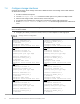
7.3 Configure VLANs and VRRP
In this section, VLANs are configured as shown in Table 2. VLAN 1611 is put in layer 3 mode by assigning an
IP address. This allows routing of in-band management and/or VM traffic. VRRP is configured to provide
gateway redundancy.
1. Create the in-band management and VM VLAN.
2. Assign a unique IP address on each switch to the VLAN interface.
3. Create a VRRP virtual router with the vrrp-group number command.
Note: VRRP is an active/standby first hop redundancy protocol. When used among VLT peers, it becomes
active/active. Both VLT peers have the VRRP virtual MAC address in their forwarding table as a local
destination address. This allows the backup VRRP router to forward intercepted frames whose destination
MAC address matches the VRRP virtual MAC address.
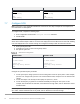
4. Set the VRRP priority. The switch with the largest priority value becomes the master VRRP router.
Note: Priority 100 is the OS10EE default value for VRRP priority. When set to 100, as is done on Leaf1B
below, the VRRP priority will not appear in the output of the show running-configuration command.
The priority number can be verified using the show vrrp brief command.
5. Assign the same VRRP virtual address to both switches.
6. Create the two storage VLANs.
Configure VLANs and VRRP
S5248F-Leaf1A
S5248F-Leaf1B
interface vlan1611
description Mgmt_and_VM
ip address 172.16.11.252/24
vrrp-group 11
priority 150
virtual-address 172.16.11.254
no shutdown
interface vlan1613
description Storage_1
no shutdown
interface vlan1614
description Storage_2
no shutdown
interface vlan1611
description Mgmt_and_VM
ip address 172.16.11.253/24
vrrp-group 11
priority 100
virtual-address 172.16.11.254
no shutdown
interface vlan1613
description Storage_1
no shutdown
interface vlan1614
description Storage_2
no shutdown