Dell PowerEdge FN 410S I/O Aggregator Getting Started Guide
Notes, Cautions, and Warnings NOTE: A NOTE indicates important information that helps you make better use of your computer. CAUTION: A CAUTION indicates either potential damage to hardware or loss of data and tells you how to avoid the problem. WARNING: A WARNING indicates a potential for property damage, personal injury, or death. Copyright © 2014 Dell Inc. All rights reserved. This product is protected by U.S. and international copyright and intellectual property laws.
Contents 1 About this Guide........................................................................................................ 5 2 Introduction............................................................................................................... 7 Product Description...............................................................................................................................7 3 Hardware Overview..................................................................................
7 Programmable-MUX Mode.................................................................................. 25 Configuring and Bringing Up the Programmable-MUX Mode..........................................................25 8 Next Steps.................................................................................................................27 9 Technical Specifications.......................................................................................
1 About this Guide This document helps you in getting started with Dell PowerEdge FN 410S I/O Aggregator. For complete installation and configuration information, refer to the documents listed below: Table 1.
Introduction 2 This document provides basic information about the Dell PowerEdge FN 410S I/O Aggregator, including how to install and perform the initial configuration. This document assumes the Dell PowerEdge FX2 server chassis is installed correctly. For the complete installation instructions, refer to the Dell PowerEdge FX2 server chassis Installation Guide .
Hardware Overview 3 This section contains information about input/output aggregator (IOA) characteristics and modular hardware configurations. Internal Ports The aggregator provides 8x10 Gigabit Ethernet internal ports. The internal ports are connected to server through the Dell PowerEdge FX2 server chassis midplane.
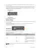
from a console terminal connected to the port through the provided serial cable (with USB UART-A to back-plane to CMC). The console port supports asynchronous data of eight data bits, one stop bit, no parity bit, and no flow control. The default baud rate is 115200 bps. The lower USB port (in the following figure) functions as an external flash drive that you can use to store configuration files, load new images, and import or export scripts or report files used in virtualization application. Figure 2.
NOTE: When the ingress air temperature exceeds 60°C, the Status LED turns Amber and a major alarm is triggered. Table 3. SFP+ Port LEDs Port LED LED Color/Display Description Link LED Off The port is down. Solid green The port is up and can transmit traffic at maximum speed. A SFP+ port can transmit at 10G. Solid amber The port is up and is transmitting traffic at lower than maximum speed. A SFP+ port is transmitting at 1G. Off No traffic is being transmitted or received on the port.
Installation 4 This switch installation procedure assume the Dell PowerEdge FX2 server chassis is installed correctly. For complete instructions for installation, refer to the Dell PowerEdge FX2 server chassis Installation Guide. • AC/DC power cord — The cord reaches from the power outlet to the Utility-panel connector. • Cabling — The cabling is routed to avoid sources of electrical noise such as radio transmitters, broadcast amplifiers, power lines, and fluorescent lighting fixtures.
5 Installing and Configuring the Aggregator After you unpack the aggregator, refer to the following flowchart for an overview of the steps you must follow to install the switch and perform the initial configuration. Figure 4.
Installing a switch in a Dell PowerEdge FX2 Server Chassis After you unpack the aggregator, slide the switch into one of the open I/O module slots in the back of a Dell PowerEdge FX2 server chassis. The Dell PowerEdge FX2 server chassis is a 2U rack-mountable chassis that holds: • Server modules: Eight quarter-width sledges or four half-width sledges.
b. 3. Set the data rate to 115200 baud. c. Set the data format to 8 data bits, 1 stop bit, and no parity. d. Set the flow control to none. e. Set the terminal emulation mode to VT100. f. Select Terminal keys for Function, Arrow, and Ctrl keys. Ensure that the setting is for Terminal keys (not Microsoft Windows keys). Connect the USB connector on the cable directly to the switch console port. The console port is located on the left side of the front end ports.
By default, the aggregator receives IP addresses from a DHCP server in the network. If you want to change the DHCP default setting, obtain the required information from your network administrator, such as: • The IP address and subnet mask of the out-of-band (OOB) interface used for remote management via Telnet, SNMP, or other management agents. • The IP address and subnet mask of the default virtual local area network (VLAN) IP address used for in-band management.
7. By default, the IP address and subnet mask of the out-of-band management interface used for remote SNMP or Telnet access is assigned by a DHCP server. You can reconfigure the default setting by specifying an IP address with the following commands: interface ManagementEthernet slot/port, where slot is 0 and port is 0. ip address ip-address/mask, where ip-address is in dotted-decimal format (A.B.C.D) and mask is a subnet mask in /prefix-length format (/xx). no shutdown enables the interface.
• • • • • • • • FCoE initiation protocol (FIP) snooping. Hybrid ports: Ports are administratively up and auto-configured to operate as hybrid ports to transmit tagged and untagged VLAN traffic. Internet small computer system interface (iSCSI) optimization. Internet group management protocol (IGMP) snooping. Jumbo frames: Ports are set to a maximum transmission unit (MTU) of 12,000 bytes. Link aggregation: All uplink ports are configured in a single link aggregation group (LAG) (LAG 128).
brought down after the specified defer-timer interval, which is 10 seconds, by default. If you have configured VLAN, you can reduce the defer time by changing the defer-timer value or remove it by using the no defer-timer command. NOTE: If installed servers do not have connectivity to a switch, check the Link Status LED of uplink ports on the aggregator. If all LEDs are on, to ensure the LACP is correctly configured, check the LACP configuration on the ToR switch that is connected to the aggregator .
• 22 To restore the default Auto-VLAN mode of operation (in which all ports are members of all 4094 VLANs) on a port, enter the auto vlan command: Dell(conf)# interface tengigabitethernet 0/2 Dell(conf-if-te-0/2)# auto vlan Installing and Configuring the Aggregator
Assembling a VLT 6 After you complete the initial configuration, the aggregator is powered up and operational. VLT is limited to two aggregators of the same SKU in the same chassis. In the aggregator, VLT is supported only using a single inter chassis link (ICL) link between the two aggregators. Cabling the VLT The following figure shows a VLT example using two aggregators in a chassis.
b. Connect the cable to the port 9 on the next aggregator. NOTE: The resulting topology allows the VLT to function as a PRIMARY/SECONDARY switch with Layer 2 multipathing, redundancy, and increased bandwidth capabilities. If the aggregator switches all reboot at approximately the same time, the aggregator with the highest MAC address is automatically elected as the primary switch. The aggregator with the next highest MAC address is elected as secondary.
Programmable-MUX Mode 7 Standalone MUX is the zero-touch auto-configuration default mode of the aggregator. If you want the flexibility to configure different settings, you must change the aggregator to Programmable MUX (PMUX) mode. PMUX mode provides a limited set of CLI commands to customize the software configuration as needed. Configuring and Bringing Up the Programmable-MUX Mode After the aggregator is operational in the default standalone mode, perform the following steps: 1.
Next Steps 8 You can customize the aggregator for use in your data center network. To perform additional switch configuration, do one of the following: • For remote out-of-band management (OOB), enter the OOB management interface IP address into a Telnet or secure shell (SSH) client and log in to the switch using the user ID and password to access the CLI. • For local management using the CLI, use the attached console connection.
Technical Specifications 9 The aggregator is an I/O module and installed with the Dell PowerEdge FX2 server chassis for communication. NOTE: Replace the battery only with same or equivalent type. Dispose of the batteries according to the manufacturer's instructions. Table 4. Environmental Parameters Parameter Specifications Operating temperature 20 °C/h (36 °F/h) Storage temperature -40° to 158°F (-40° to 70°C) Relative humidity (Storage) 5% to 95% RH with 33 °C (91 °F) maximum dew point.