
Deployment Guide


• A dynamic threshold handles intermittent trac bursts and varies based on the number of PFC priorities contending for buers, while a
static threshold places an upper limit on the transmit time of a queue after receiving a message to pause a specied priority. PFC trac
is paused only after surpassing both static and dynamic thresholds for the priority specied for the port.
• By default, PFC is enabled when you enabled DCB. When you enable DCB globally, you cannot simultaneously enable TX and RX on the
interface for ow control and link-level ow control is disabled.
• Buer space is allocated and de-allocated only when you congure a PFC priority on the port.
• PFC delay constraints place an upper limit on the transmit time of a queue after receiving a message to pause a specied priority.
• By default, PFC is enabled on an interface with no dot1p priorities congured. You can congure the PFC priorities if the switch
negotiates with a remote peer using DCBX. During DCBX negotiation with a remote peer:
• DCBx communicates with the remote peer by link layer discovery protocol (LLDP) type, length, value (TLV) to determine current
policies, such as PFC support and enhanced transmission selection (ETS) BW allocation.
• If the negotiation succeeds and the port is in DCBX Willing mode to receive a peer conguration, PFC parameters from the peer are
used to congured PFC priorities on the port. If you enable the link-level ow control mechanism on the interface, DCBX
negotiation with a peer is not performed.
• If the negotiation fails and PFC is enabled on the port, any user-congured PFC input policies are applied. If no PFC dcb-map has
been previously applied, the PFC default setting is used (no priorities congured). If you do not enable PFC on an interface, you can
enable the 802.3x link-level pause function. By default, the link-level pause is disabled, when you disable DCBx and PFC. If no PFC
dcb-map has been applied on the interface, the default PFC settings are used.
• PFC supports buering to receive data that continues to arrive on an interface while the remote system reacts to the PFC operation.
• PFC uses the DCB MIB IEEE802.1azd2.5 and the PFC MIB IEEE802.1bb-d2.2.
If DCBx negotiation is not successful (for example, due to a version or TLV mismatch), DCBx is disabled and you cannot enable PFC or
ETS.
Enhanced Transmission Selection
Enhanced transmission selection (ETS) supports optimized bandwidth allocation between trac types in multiprotocol (Ethernet, FCoE,
SCSI) links.
ETS allows you to divide trac according to its 802.1p priority into dierent priority groups (trac classes) and congure bandwidth
allocation and queue scheduling for each group to ensure that each trac type is correctly prioritized and receives its required bandwidth.
For example, you can prioritize low-latency storage or server cluster trac in a trac class to receive more bandwidth and restrict best-
eort LAN trac assigned to a dierent trac class.
Although you can congure strict-priority queue scheduling for a priority group, ETS introduces exibility that allows the bandwidth
allocated to each priority group to be dynamically managed according to the amount of LAN, storage, and server trac in a ow. Unused
bandwidth is dynamically allocated to prioritized priority groups. Trac is queued according to its 802.1p priority assignment, while exible
bandwidth allocation and the congured queue-scheduling for a priority group is supported.
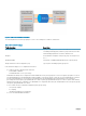
The following gure shows how ETS allows you to allocate bandwidth when dierent trac types are classed according to 802.1p priority
and mapped to priority groups.
Data Center Bridging (DCB)
39