
Deployment Guide


As a result, PFC and lossless port queues are disabled on 802.1p priorities, and all priorities are mapped to the same priority queue and
equally share port bandwidth.
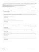
• To change the ETS bandwidth allocation congured for a priority group in a DCB map, do not modify the existing DCB map
conguration. Instead, create a new DCB map with the desired PFC and ETS settings, and apply the new map to the interfaces to
override the previous DCB map settings. Then, delete the original dot1p priority-to-priority group mapping.
• If you delete the dot1p priority-to-priority group mapping (no priority pgid command) before you apply the new DCB map, the
default PFC and ETS parameters are applied on the interfaces. This change may create a DCB mismatch with peer DCB devices and
interrupt the network operation.
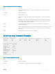
Applying a DCB Map on Server-facing Ethernet Ports
You can apply a DCB map only on a physical Ethernet interface and can apply only one DCB map per interface.
1 Enter CONFIGURATION mode on a server-facing port or port channel to apply a DCB map.
You cannot apply a DCB map on a port channel. However, you can apply a DCB map on the ports that are members of the port
channel.
CONFIGURATION mode
interface {tengigabitEthernet slot/port }
2 Apply the DCB map on an Ethernet port or port channel. The port is congured with the PFC and ETS settings in the DCB map.
Repeat this step to apply a DCB map to more than one port or port channel.
INTERFACE mode
dcb-map name
Dell# interface tengigabitEthernet 0/0
Dell(config-if-te-0/0)# dcb-map SAN_DCB1
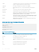
Creating an FCoE VLAN
Create a dedicated VLAN to send and receive Fibre Channel trac over FCoE links between servers and a fabric over an NPG. The NPG
receives FCoE trac and forwards decapsulated FC frames over FC links to SAN switches in a specied fabric.
1 Create the dedicated VLAN for FCoE trac. Range: 2–4094.
VLAN 1002 is commonly used to transmit FCoE trac.
CONFIGURATION mode
interface vlan vlan-id
When you apply an FCoE map to an Ethernet port , the port is automatically congured as a tagged member of the FCoE VLAN.
Creating an FCoE Map
An FCoE map consists of:
• An association between the dedicated VLAN, used to carry FCoE trac, and the SAN fabric where the storage arrays are installed. Use
a separate FCoE VLAN for each fabric to which the FCoE trac is forwarded. Any non-FCoE trac sent on a dedicated FCoE VLAN is
dropped.
324
NPIV Proxy Gateway