
Reference Guide

To enable DCB with PFC buffers on a switch, enter the following commands, save the configuration, and
reboot the system to allow the changes to take effect.
1. Enable DCB.
CONFIGURATION mode
dcb enable
2. Set PFC buffering on the DCB stack unit.
CONFIGURATION mode
dcb stack-unit all pfc-buffering pfc-ports 64 pfc-queues 2
NOTE: To save the pfc buffering configuration changes, save the configuration and reboot the
system.
NOTE: Dell Networking OS Behavior: DCB is not supported if you enable link-level flow control on
one or more interfaces. For more information, refer to Flow Control Using Ethernet Pause Frames.
Data Center Bridging: Auto-DCB-Enable Mode
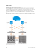
On an Aggregator in standalone or VLT modes, the default mode of operation for data center bridging on
Ethernet ports is auto-DCB-enable mode. In this mode, Aggregator ports detect whether peer devices
support CEE or not, and enable ETS and PFC or link-level flow control accordingly:
• Interfaces come up with DCB disabled and link-level flow control enabled to control data
transmission between the Aggregator and other network devices (see Flow Control Using Ethernet
Pause Frames). When DCB is disabled on an interface, PFC, and ETS are also disabled.
• When DCBx protocol packets are received, interfaces automatically enable DCB and disable link-level
flow control.
DCB is required for PFC, ETS, DCBx, and FCoE initialization protocol (FIP) snooping to operate.
NOTE: Normally, interfaces do not flap when DCB is automatically enabled.
DCB processes VLAN-tagged packets and dot1p priority values. Untagged packets are treated with a
dot1p priority of 0.
For DCB to operate effectively, ingress traffic is classified according to its dot1p priority so that it maps to
different data queues. The dot1p-queue assignments used on an Aggregator are shown in Table 6-1 in
dcb enable auto-detect on-next-reload Command Example QoS dot1p Traffic Classification and Queue
Assignment.
When DCB is Disabled (Default) By default, Aggregator interfaces operate with DCB disabled and link-
level flow control enabled. When an interface comes up, it is automatically configured with:
• Flow control enabled on input interfaces.
• A DCB-MAP policy is applied with PFC disabled.
The following example shows a default interface configuration with DCB disabled and link-level flow
control enabled.
show interfaces Command Example: DCB disabled and Flow Control enabled
Dell#show running-config interface te 0/4
!
Data Center Bridging (DCB)
41