
Users Guide

Hierarchical Scheduling in ETS Output Policies
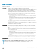
ETS supports up to three levels of hierarchical scheduling.
For example, you can apply ETS output policies with the following congurations:
Priority group 1 Assigns trac to one priority queue with 20% of the link bandwidth and strict-priority scheduling.
Priority group 2 Assigns trac to one priority queue with 30% of the link bandwidth.
Priority group 3 Assigns trac to two priority queues with 50% of the link bandwidth and strict-priority scheduling.
In this example, the congured ETS bandwidth allocation and scheduler behavior is as follows:
Unused bandwidth
usage:
Normally, if there is no trac or unused bandwidth for a priority group, the bandwidth allocated to the group is
distributed to the other priority groups according to the bandwidth percentage allocated to each group. However,
when three priority groups with dierent bandwidth allocations are used on an interface:
• If priority group 3 has free bandwidth, it is distributed as follows: 20% of the free bandwidth to priority group 1
and 30% of the free bandwidth to priority group 2.
• If priority group 1 or 2 has free bandwidth, (20 + 30)% of the free bandwidth is distributed to priority group 3.
Priority groups 1 and 2 retain whatever free bandwidth remains up to the (20+ 30)%.
Strict-priority
groups:
If two priority groups have strict-priority scheduling, trac assigned from the priority group with the higher
priority-queue number is scheduled rst. However, when three priority groups are used and two groups have strict-
priority scheduling (such as groups 1 and 3 in the example), the strict priority group whose trac is mapped to one
queue takes precedence over the strict priority group whose trac is mapped to two queues.
Therefore, in this example, scheduling trac to priority group 1 (mapped to one strict-priority queue) takes precedence over scheduling
trac to priority group 3 (mapped to two strict-priority queues).
DCBx Operation
The data center bridging exchange protocol (DCBx) is used by DCB devices to exchange conguration information with directly connected
peers using the link layer discovery protocol (LLDP) protocol. DCBx can detect the misconguration of a peer DCB device, and optionally,
congure peer DCB devices with DCB feature settings to ensure consistent operation in a data center network.
DCBx is a prerequisite for using DCB features, such as priority-based ow control (PFC) and enhanced trac selection (ETS), to exchange
link-level congurations in a converged Ethernet environment. DCBx is also deployed in topologies that support lossless operation for FCoE
or iSCSI trac. In these scenarios, all network devices are DCBx-enabled (DCBx is enabled end-to-end).
The following versions of DCBx are supported on an Aggregator: CIN, CEE, and IEEE2.5.
DCBx requires the LLDP to be enabled on all DCB devices.
DCBx Operation
DCBx performs the following operations:
• Discovers DCB conguration (such as PFC and ETS) in a peer device.
• Detects DCB mis-conguration in a peer device; that is, when DCB features are not compatibly congured on a peer device and the
local switch. Mis-conguration detection is feature-specic because some DCB features support asymmetric conguration.
• Recongures a peer device with the DCB conguration from its conguration source if the peer device is willing to accept
conguration.
• Accepts the DCB conguration from a peer if a DCBx port is in “willing” mode to accept a peer’s DCB settings and then internally
propagates the received DCB conguration to its peer ports.
48
Data Center Bridging (DCB)