
Users Guide


• With FC Flex IO modules on an IOA, the following DCB maps are applied on all of the ENode facing ports.
• dcb-map: SAN_DCB_MAP
• priority-group 0 bandwidth 30 pfc o
• priority-group 1 bandwidth 30 pfc o
• priority-group 2 bandwidth 40 pfc on
• priority-pgid 0 0 0 2 1 0 0 0
• On I/O Aggregators, uplink failure detection (UFD) is disabled if FC Flex IO module is present to allow server ports to
communicate with the FC fabric even when the Ethernet upstream ports are not operationally up.
• Ensure that the NPIV functionality is enabled on the upstream switches that operate as FC switches or FCoE forwarders (FCF)
before you connect the FC port of the I/O Aggregator to these upstream switches.
• While storage trac traverses through FC Flex IO modules and the Ethernet uplink port-channel status changes (with DCB
enabled on an adjacent switch), FCoE trac is disrupted. This problem does not occur if Ethernet trac is not involved and only
FCoE trac is transmitted. Also, if DCB on the ToR switch is disabled, trac disruption does not occur.
Port Numbering for FC Flex IO Modules
Even-numbered ports are at the bottom of the I/O panel and for modules odd-numbered ports are at the top of the I/O panel. When
installed in a PowerEdge M1000e Enclosure, the I/O Aggregator ports are numbered 33 to 56 from the bottom to the top of the
switch. The following port numbering convention applies to the FC Flex IO module:
• In expansion slot 0, the ports are numbered 41 to 44.
• In expansion slot 1, the ports are numbered 49 to 52.
Installing the Optics
The following optical ports are supported on the FC Flex IO module using one of the supported breakout cables:
• 4G or 8G Fibre Channel small form-factor pluggable plus (SFP+) optics module and LC connectors over a distance of 150
meters.
• 4G or 8G Fibre Channel SFP+ optics module and LC connectors over a distance of 4 km.
CAUTION:
Electrostatic discharge (ESD) damage can occur if the components are mishandled. Always wear an ESD-preventive wrist or
heel ground strap when handling the FC Flex IO module and its components.
WARNING: When working with optical bres, follow all the warning labels and always wear eye protection. Never look
directly into the end of a terminated or unterminated bre or connector as it may cause eye damage.
1.
• Position the optic so it is in the correct position. The optic has a key that prevents it from being inserted incorrectly.
• Insert the optic into the port until it gently snaps into place.
NOTE:
1. When you cable the ports, be sure not to interfere with the airow from the small vent holes above and below the ports.
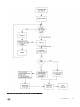
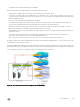
Processing of Data Trac
The Dell Networking OS determines the module type that is plugged into the slot. Based on the module type, the software performs
the appropriate tasks. The FC Flex IO module encapsulates and decapsulates the FCoE frames. The module directly switches any
non-FCoE or non-FIP trac, and only FCoE frames are processed and transmitted out of the Ethernet network.
When the external device sends FCoE data frames to the switch that contains the FC Flex IO module, the destination MAC address
represents one of the Ethernet MAC addresses assigned to FC ports. Based on the destination address, the FCoE header is
removed from the incoming packet and the FC frame is transmitted out of the FC port. The ow control mechanism is performed
using per-priority ow control to ensure that frame loss does not occur owing to congestion of frames.
FC Flex IO Modules
255