
Users Guide


By default, if all upstream interfaces in an uplink-state group go down, all downstream interfaces in the same uplink-state group are
put into a Link-Down state.
Using UFD, you can congure the automatic recovery of downstream ports in an uplink-state group when the link status of an
upstream port changes. The tracking of upstream link status does not have a major impact on central processing unit (CPU) usage.
UFD and NIC Teaming
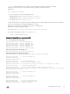
To implement a rapid failover solution, you can use uplink failure detection on a switch with network adapter teaming on a server.
For more information, refer to Network Interface Controller (NIC) Teaming.
For example, as shown previously, the switch/ router with UFD detects the uplink failure and automatically disables the associated
downstream link port to the server. To continue to transmit trac upstream, the server with NIC teaming detects the disabled link
and automatically switches over to the backup link in order to continue to transmit trac upstream.
Important Points to Remember
When you congure UFD, the following conditions apply.
• You can congure up to 16 uplink-state groups. By default, no uplink state groups are created in PMUX mode and uplink state
group 1 is created in Standalone and VLT modes.
– An uplink-state group is considered to be operationally up if it has at least one upstream interface in the Link-Up state.
– An uplink-state group is considered to be operationally down if it has no upstream interfaces in the Link-Up state. No uplink-
state tracking is performed when a group is disabled or in an Operationally Down state.
• You can assign physical port or port-channel interfaces to an uplink-state group in PMUX mode.
– You can assign an interface to only one uplink-state group. Congure each interface assigned to an uplink-state group as
either an upstream or downstream interface, but not both.
– You can assign individual member ports of a port channel to the group. An uplink-state group can contain either the member
ports of a port channel or the port channel itself, but not both.
– If you assign a port channel as an upstream interface, the port channel interface enters a Link-Down state when the number
of port-channel member interfaces in a Link-Up state drops below the congured minimum number of members
parameter.
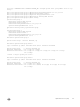
• If one of the upstream interfaces in an uplink-state group goes down, either a user-congurable set of downstream ports or all
the downstream ports in the group are put in an Operationally Down state with an UFD Disabled error. The order in which
downstream ports are disabled is from the lowest numbered port to the highest.
– If one of the upstream interfaces in an uplink-state group that was down comes up, the set of UFD-disabled downstream
ports (which were previously disabled due to this upstream port going down) is brought up and the UFD Disabled error is
cleared.
• If you disable an uplink-state group, the downstream interfaces are not disabled regardless of the state of the upstream
interfaces.
– If an uplink-state group has no upstream interfaces assigned, you cannot disable downstream interfaces when an upstream
link goes down.
• To enable the debug messages for events related to a specied uplink-state group or all groups, use the debug uplink-
state-group [group-id] command, where the group-id is from 1 to 16.
– To turn o debugging event messages, use the no debug uplink-state-group [group-id] command.
– For an example of debug log message, refer to Clearing a UFD-Disabled Interface.
Uplink Failure Detection (SMUX mode)
In Standalone or VLT modes, by default, all the server-facing ports are tracked by the operational status of the uplink LAG. If the
uplink LAG goes down, the aggregator loses its connectivity and is no longer operational. All the server-facing ports are brought
down after the specied defer-timer interval, which is 10 seconds by default. If you have congured VLAN, you can reduce the defer
time by changing the defer-timer value or remove it by using the
no defer-timer command.
Uplink Failure Detection (UFD)
231