
Users Guide


How Uplink Failure Detection Works
UFD creates an association between upstream and downstream interfaces. The association of uplink and downlink interfaces is
called an
uplink-state group.
An interface in an uplink-state group can be a physical interface or a port-channel (LAG) aggregation of physical interfaces.
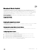
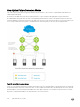
An enabled uplink-state group tracks the state of all assigned upstream interfaces. Failure on an upstream interface results in the
automatic disabling of downstream interfaces in the uplink-state group. As a result, downstream devices can execute the protection
or recovery procedures they have in place to establish alternate connectivity paths, as shown in the following illustration.
Figure 33. Uplink Failure Detection Example
If only one of the upstream interfaces in an uplink-state group goes down, a specied number of downstream ports associated with
the upstream interface are put into a Link-Down state. You can congure this number and is calculated by the ratio of the upstream
port bandwidth to the downstream port bandwidth in the same uplink-state group. This calculation ensures that there is no trac
drops due to insucient bandwidth on the upstream links to the routers/switches.
230
Uplink Failure Detection (UFD)