
Reference Guide


56 | Data Center Bridging (DCB)
www.dell.com | support.dell.com
• A DCB input policy with PFC disabled
• A DCB output policy with ETS disabled
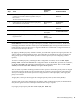
Figure 5-4 shows a default interface configuration with DCB enabled and link-level flow control enabled.
When the first Aggregator interface with DCB disabled receives an LLDP packet with a DCBx TLV
advertisement, DCB is enabled on the interface and on all uplink interfaces.
Figure 5-4. show interfaces Command Example: DCB disabled and Flow Control enabled
When DCB is Enabled
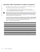
When a server-facing interface receives DCBx protocol packets, it automatically enables DCB and
disables link-level flow control. The DCB input and output policies and the flow control configuration are
removed as shown in Figure 5-5.
When no DCBx TLVs are received on a DCB-enabled interface for 180 seconds, DCB is automatically
disabled and flow control is re-enabled. When all 10GbE server-facing interfaces have DCB disabled,
DCB is also disabled on all 40GbE uplink interfaces.
Figure 5-5. show interfaces Command Example: DCB enabled and Flow Control disabled
FTOS#show interfaces tengigabitethernet 0/2
interface TenGigabitEthernet 0/2
mtu 12000
portmode hybrid
switchport
auto vlan
flowcontrol rx on tx off
dcb-policy input smux-dcb-in
dcb-policy output smux-dcb-out
!
protocol lldp
advertise management-tlv system-name
dcbx port-role auto-downstream
no shutdown
FTOS#show interfaces tengigabitethernet 0/2
interface TenGigabitEthernet 0/2
mtu 12000
auto vlan
!
port-channel-protocol LACP
port-channel 1 mode active
!
protocol lldp
advertise management-tlv system-name
dcbx port-role auto-downstream
no shutdown