
Reference Guide


Data Center Bridging (DCB) | 55
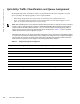
Figure 5-3. DCB PFC and ETS Traffic Handling
Data Center Bridging: Auto-DCB-Enable Mode
On an Aggregator in standalone, stacking, or VLT mode, the default mode of operation for data center
bridging on Ethernet ports is auto-DCB-enable mode. In this mode, Aggregator ports detect whether peer
devices support CEE or not, and enable DCBx and PFC or link-level flow control accordingly:
• Interfaces come up with DCB disabled and link-level flow control enabled to control data transmission
between the Aggregator and other network devices (see Flow Control Using Ethernet Pause Frames).
When DCB is disabled on an interface, PFC, ETS, and DCBx are also disabled.
• When DCBx protocol packets are received, interfaces automatically enable DCB and disable link-level
flow control.
DCB is required for PFC, ETS, DCBx, and FCoE initialization protocol (FIP) snooping to operate.
DCB processes VLAN-tagged packets and dot1p priority values. Untagged packets are treated with a
dot1p priority of 0.
For DCB to operate effectively, ingress traffic is classified according to its dot1p priority so that it maps to
different data queues. The dot1p-queue assignments used on an Aggregator are shown in Table 5-1 in dcb
enable auto-detect on-next-reload Command Example.
When DCB is Disabled (Default)
By default, Aggregator interfaces operate with DCB disabled and link-level flow control enabled. When an
interface comes up, it is automatically configured with:
• Flow control enabled on input interfaces
Note: Normally, interfaces do not flap when DCB is automatically enabled.
Switching
Apply PFC no-drop handling
for lossless queues of
ingress priority traffic
Apply QoS traffic
classification using
dot1p priority and
map to queue
Ingress Traffic
Egress Traffic
Apply ETS bandwidth
allocation and
scheduling to
priority-group traffic
Transmit ETS-handled
priority traffic
on egress queue
Map priority traffic
to ETS priority
groups