
Reference Guide


300 | Virtual Link Trunking (VLT)
www.dell.com | support.dell.com
VLT Configuration Procedure
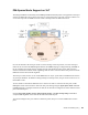
To configure virtual link trunking and create a VLT domain in which two S4810 or Z9000 switches are
physically connected and treated as a single port channel by access devices, you must configure the
following settings on each VLT peer device:
Prerequisite: Before you begin, make sure that both VLT peer switches are running the same FTOS
version and are configured for RSTP as described in Chapter 27, Rapid Spanning Tree Protocol (RSTP).
For VRRP operation, ensure that VRRP groups and L3 routing on each VLT peer are configured as
described in Virtual Router Redundancy Protocol (VRRP).
1. Configure the VLT interconnect for the VLT domain. The primary and secondary switch roles in the
VLT domain are automatically assigned after both sides of the VLTi are configured.
2. Enable VLT and create a VLT domain ID. VLT automatically selects a system MAC address.
3. Configure a backup link for the VLT domain.
4. (Optional) Manually reconfigure default VLT settings, such as MAC address and VLT primary/
secondary roles.
5. Connect the peer switches in a VLT domain to an attached access device (switch or server).
Note: If a third-party ToR unit is used, Dell Networking recommends using static LAGs on the VLTi
between VLT peers to avoid potential problems if the VLT peers are rebooted.
Configure a VLT interconnect
Step Task Command Syntax Command Mode
1 Configure the port channel to be used for the VLT
interconnect on a VLT switch and enter interface
configuration mode.
Enter the same port-channel number configured with the
peer-link port-channel command.
interface port-channel
id-number
CONFIGURATION
Note: To be included in the VLTi, the port channel must be in default mode (no switchport or VLAN
assigned).
2 Remove an IP address from the interface.
no ip address
INTERFACE
PORT-CHANNEL
3 Add one or more port interfaces to the port channel.
interface specifies one of the following interface types:
1-Gigabit Ethernet: Enter
gigabitethernet slot/port.
10-Gigabit Ethernet: Enter
tengigabitethernet slot/port.
channel-member interface
INTERFACE
PORT-CHANNEL
4 Ensure that the port channel is active.
no shutdown
INTERFACE
PORT-CHANNEL
5 Repeat Steps 1 to 4 on the VLT peer switch to configure the VLT interconnect.