
Reference Guide


208 | Simple Network Management Protocol (SNMP)
www.dell.com | support.dell.com
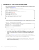
Starting from the least significant bit (LSB):
• the first 14 bits represent the card type
• the next 4 bits represent the interface type
• the next 7 bits represent the port number
• the next 5 bits represent the slot number
• the next 1 bit is 0 for a physical interface and 1 for a logical interface
• the next 1 bit is unused
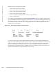
For example, the index 44634369 is 10101010010001000100000001 in binary. The binary interface index
for TenGigabitEthernet 0/41 of an Aggregator is shown in Figure 15-13. Notice that the physical/logical bit
and the final, unused bit are not given. The interface is physical, so this must be represented by a 0 bit, and
the unused bit is always 0. These two bits are not given because they are the most significant bits, and
leading zeros are often omitted.
Figure 15-13. Binary Representation of Interface Index
For interface indexing, slot and port numbering begins with binary one. If the Dell Networking system
begins slot and port numbering from 0, binary 1 represents slot and port 0. In S4810, the first interface is 0/
0, but in the Aggregator the first interface is 0/1. Hence, in the Aggregator 0/0s Ifindex is unused and
Ifindex creation logic is not changed. Because Zero is reserved for logical interfaces, it starts from 1. For
the first interface, port number is set to 1. Adding it causes an increment by 1 for the next interfaces, so it
only starts from 2.Therefore, the port number is set to 42 for 0/41.